REV.-A
5.
6.
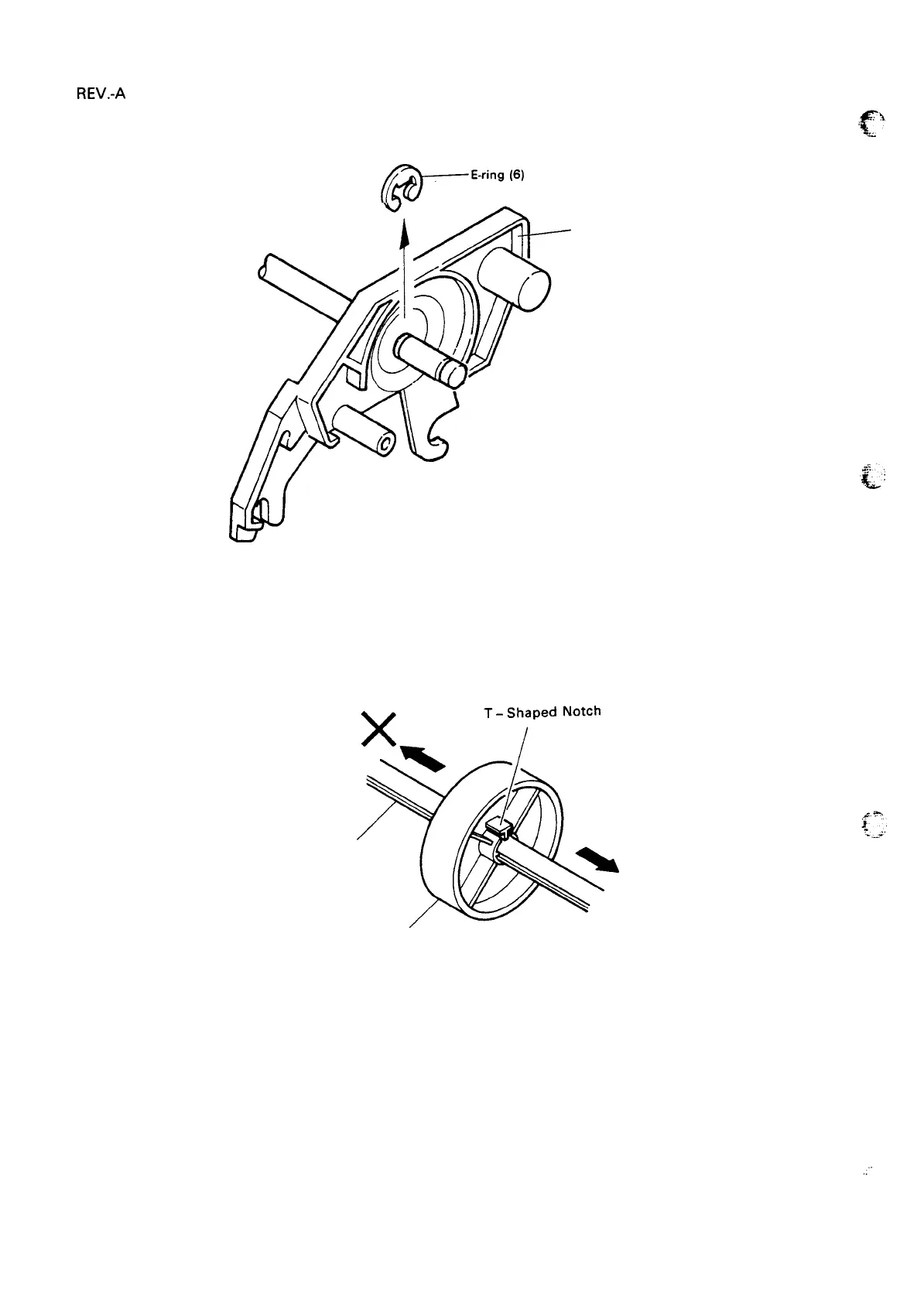
Remove the E-ring (6) from the sprocket shaft, then remove sprocket mounting plate R.
(@-ring’”
Sprocket
Mounting Plate R
Figure 3-15. Removal of Sprocket Mounting Plate.
From the sprocket shaft and the sprocket guide shaft, pull and remove sprocket set R, the paper guide
roller, and sprocket set L. In separating the paper guide roller, pull in the same direction as the side
on which the T-shaped notch is located. (When reassembling, insert from the same side.)
Sprocket Shaft
o
Paper-Guide Roller’
Figure 3-16. Direction of Paper Guide Roller Removal
,.”’
3-18

 Loading...


