REV.-A
4.1 GENERAL REPAIR INFORMATION
This chapter describes the procedures for removing, replacing, and adjusting the main components
of the LX-8 10/850.
CAUTION
● Prior to beginning any of these procedures, be certain that the AC power
cord is disconnected.
● To help prevent hands from being cut by the printer mechanism or sharp plate edges, wear
gloves when performing these procedures.
WARNING
. The printer mechanism, boards, and other parts are sometimes held in place with plastic clips
rather than screws. Be careful not to damage these clips when removing them.
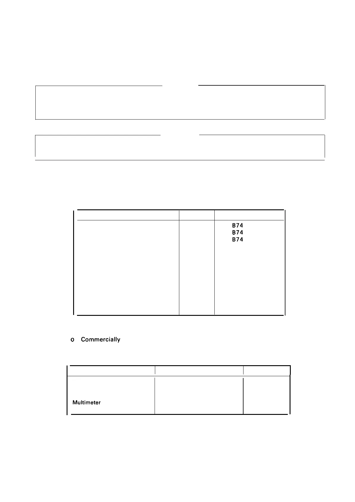
Tables 4-1 and 4-2 list tools and measuring instruments recommended for carrying out disassembly
and repair.
Table 4-1. Repair Tools
Description
Type
Pert No.
Brush No. 1
0
B74
1400200
Brush No. 2
0
B74
1400100
Cleaning Brush
o
B74
1600100
Round-nose pliers
o
B740400100
Diagonal cutting nipper
o
B740500100
Tweezers
o
B64 1000100
Electric soldering iron
o
B7402OO1OO
E-ring holder #2.5
●
o
B740800400
E-ring holder #5
o
B740800700
Philips screwdriver No. 2
0
B743800200
Screwdriver No. O
0
B743800300
Thickness gauge (0.44)
o
Thickness gauge (0.47)
o
(*) indicates the tool used to attach the (2.3 mm) E-ring.
o
= Commercially available
Table 4-2. Measuring Instruments
Description
Specification
Class
NOTES: 1.
2.
Oscilloscope
50 MHz
A
Tester A
Slide calipers
A
Muitimeter
B
Logic Analyzer
B
NOTE: A = Required; B = Recommended
4-1

 Loading...


