REV.-A
SLA7020M
Phase Signal Input Circuit
Although most step-motor
control IC’S input 4-phase data directly, the
SLA7020M
requires a special
type of phase data.
In the case of
2-2 phase excitation:
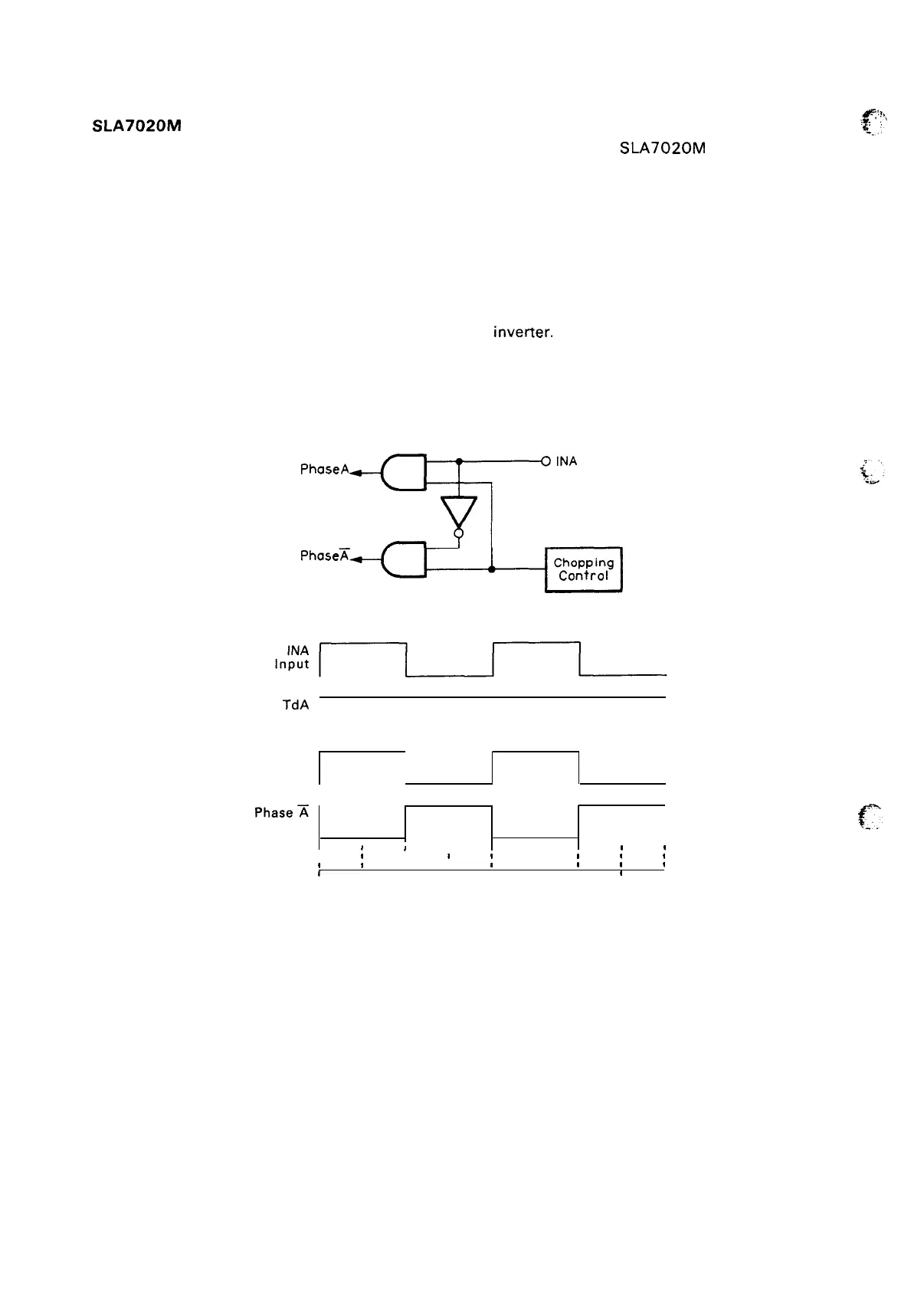
Figure 2-28 shows the excitation signal input circuit.
The A-phase-side excitation signal input is via a single line. The output is divided among non-inverted
A-phase output and A-phase output passed through an
inverter. Therefore, the A-phase output side will
be ON when the excitation input signal is HIGH. The A-phase output side will be ON when the excitation
input signal is LOW.
Figure 2-29 shows the timing chart for 2-2 phase excitation.
PhoseA
output
output
Figure 2-28. Phase Data Input Circuit (2-2 Phase)
TdA
Input
Phase A
I
Phase~
,
I
J
1
1
1
I
1
8
1
I I
1
1
I I
I I
1
1
#
1
1 1
I
r
1 1
1
I
1
i
1
2’3 4 1
2 3 4’
Figure 2-29. Phase Signal Timing Chart (2-2 Phase)
2-26

 Loading...


