EasyManuals Logo

Epson LX-810 Technical Manual

Epson LX-810
176 pages
To Next Page IconTo Next Page
To Previous Page IconTo Previous Page
Page #63 background imageLoading...
Page #63 background image
REV.-A
In the case of 1-2 phase excitation:
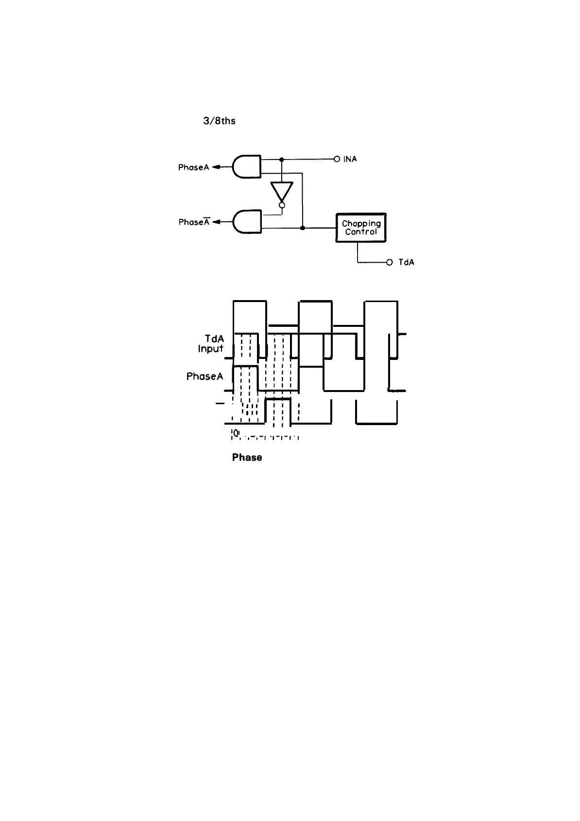
Figure 2-30 shows the excitation signal input circuit. When the Td terminal is LOW, the SLA702M can
cut off the output current. By using this function, the unaltered 2-phase excitation signal can cause the
1-2 phase excitation to be on
3/8ths
of the time, which is a suitable value.
Figure 2-31 shows the timing chart.
““’’’-r’”’
Figure 2-30. Phase Data Input Circuit (l-2 Phase)
INA
Ill
input
Ill
Ill
Ill
, .
TdA
;;
ii
4
-
II
t
d
a
h
II
~
—1111
I
PhaseA
i
~
~
~
;;
;
1!11
;;
I
I
1
I
QI
11213141516171
1,,,11111
Figure 2-31. Phasa Signal Timing Chart (l-2 Phase)
2-27

Table of Contents

Other manuals for Epson LX-810

Questions and Answers:

Question and Answer IconNeed help?

Do you have a question about the Epson LX-810 and is the answer not in the manual?

Epson LX-810 Specifications

General IconGeneral
Print MethodImpact dot matrix
Number of Pins9
Character Sets96 characters (USASCII)
Line Spacing1/6 inch
Paper PathRear
InterfaceCentronics parallel
Noise Level55 dB (A)

Related product manuals