REV.-A
Reference Voltage Generation Circuit
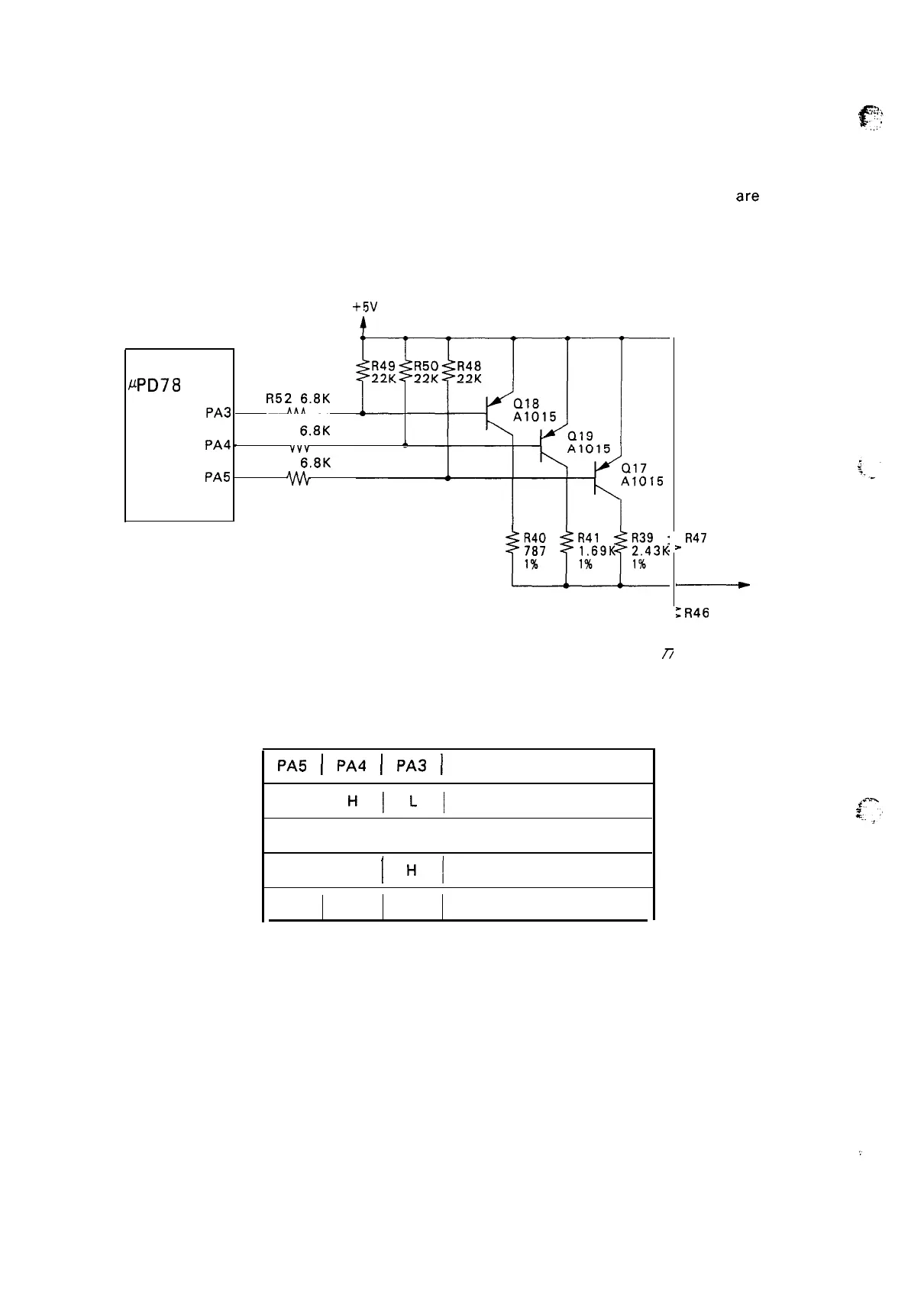
Figure 2-32 shows the reference voltage generation circuit and Table 2-3 shows the reference voltage.
The reference voltage generation circuit is shown in Figure 2-32, the reference voltages are shown in
Table 2-3. The SLA7020M drives the stepping motor based on current proportional to the reference
voltages set here. There are four stages of reference voltage values (motor drive current values), and
these are switched to correspond to the drive speed of the motor.
+5V
CPU
LLPD78
10HG
(2 c )
~A3
4
q,y
5
R53
6.8K
PA4
v
A
Vvv
6
R51
6.8K
PA5
n
Figure 2-32. Reference Voltage Generation Circuit
Table 2-3. Reference Voltage
PA5
I
PA4
I
PA3
I
Reference Voltage
H]
H\Ll
0.634 V
H
I
L
I
H
I
0.359
v
L
I
H
I
HI
0.280 V
H
H
H
0.089 V
Z
R47
* 5.49K
1%
~
Vref
E
R46
“ 100
1%
7
,,.
2-28

 Loading...


