REV.-A
Constant Current Drive Circuit
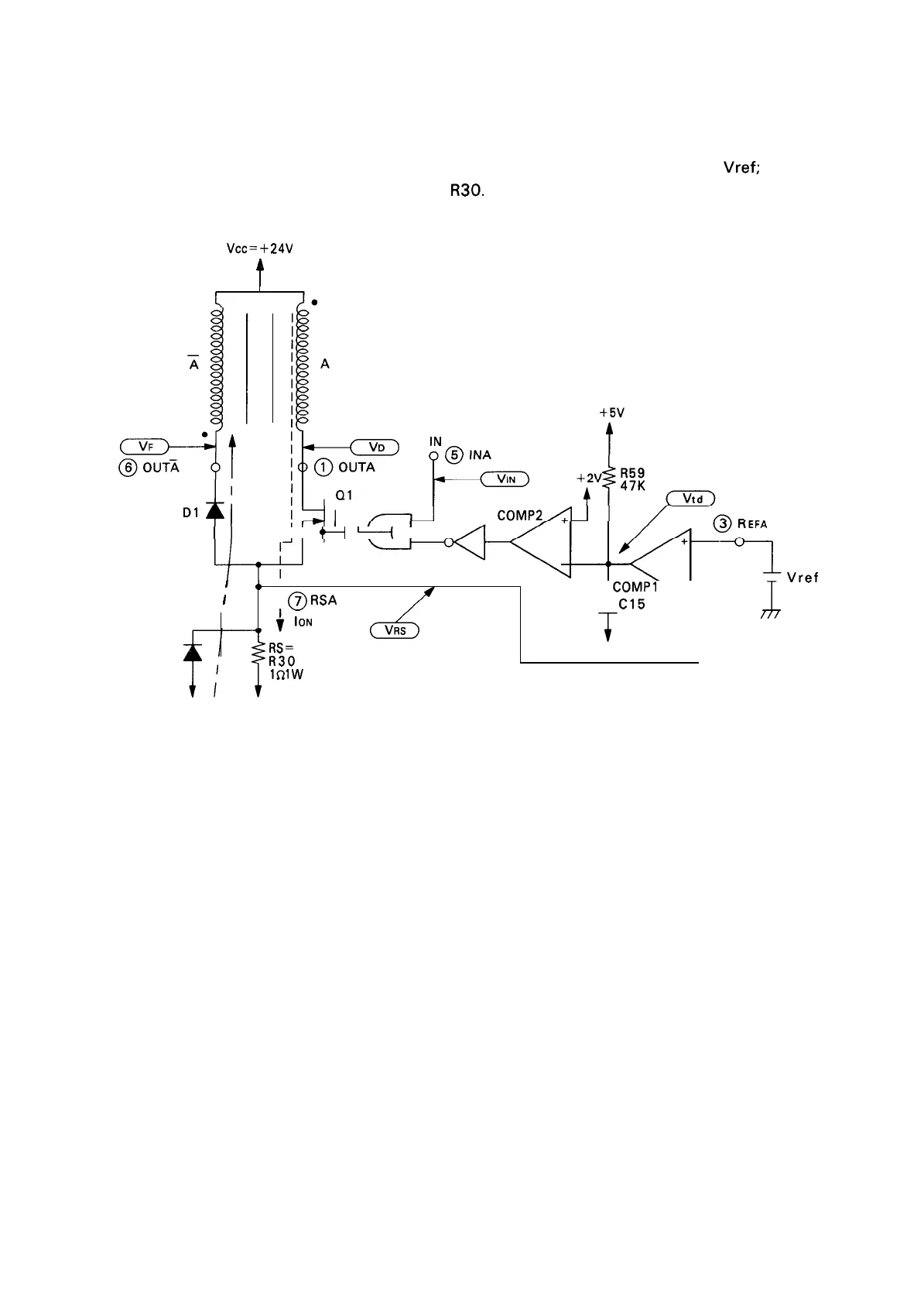
The constant current drive circuit is shown in Figure 2-33 (for A-phase only), and the waveforms for
each part are shown in Figure 2-34. In Figure 2-33, the reference voltage is indicated by
Vref;
this voltage
determines the peak current through resistance
R30.
Resistance R59 and capacitance C 15 determine
the OFF time of the chopper.
vcc=
+24V
t
II
!
+-l
+
I .
/1
1
b
,
IOFF
1
1
c
)
“1
COMP1
-
I
@
RSA
C15
L
i
ION
J
470p
D5
RS=
R30
Gp
lsll
w
Gp Gp
Vref
Figure 2-33. Constant Current Control Circuit
2-29

 Loading...


