REV.-A
WWF
:
.-.-J---------.---
---------
0{
I
VRS
I
-.-.--
------- ------- ?------ ------- -
1
Vb
:
,
------ : ----- . : - . ---- s -----------------------
Q{
#
VT
1
,
0
----
;-----------------
0
VG
8
0
1
Zvcc
---
~;
‘4
—
0{
,
,
VG
0{
VF
,
1
;
1P
o~
km
o
o{
IWF
o
0
Icc
[
o
. --- L -----------
,
,
,
.
,
,
I
,
----------------
#-
------
------
b
------
t
I
t
I
*
F
t
1
,
1
t
i
I
t
I
I
t
, -----------------
-------
.. -----
.------
.------
,------ -------- -
,
1
1
A
,
4
1
I
to
tl
t2
t3
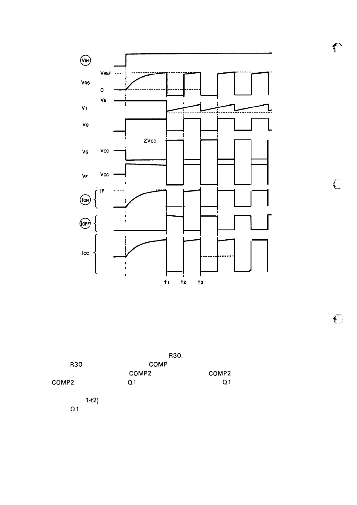
Figure 2-34. Waveforms
The circuit’s constant current control process is shown above.
.p
.
.,
Peak current detection (to-t 1)
(1) When excitation input IN goes ON, so does MOS FET Q 1. The A-coil excitation current I
ON then
flows along route –.
(2)
As I
ON increases, so does the voltage at
R30.
(3)
When
R30
voltage exceeds Vref, COMP 1 inverts, and the TD voltage falls to near zero.
(4) When
VTD drops below the
COMP2
threshold voltage,
COMP2
inverts.
(5)
COMP2
inversion causes
Q1
gate voltage to go LOW, and Q1 goes OFF.
Chopper off time (t
l-t2)
(6)
When
Q1 goes OFF, reverse potential is generated in the motor coil, causing the coil current
route to switch from I
ON to IOFF.
2-30

 Loading...


