Installation 2. Installation
40 RC700 Series Rev.3
Checking Emergency Stop Switch Operation
Refer to 4.2 De
velopment PC and Controller Connection and connect the development PC
and Controller before checking the function.
Once the Emergency Stop switch is connected to the EMERGENCY connector, continue
the following procedure to make sure that the switch functions properly.
Control Unit RC700
(1) Turn ON the Controller to boot the Controller software while pressing the Emergency
Stop switch.
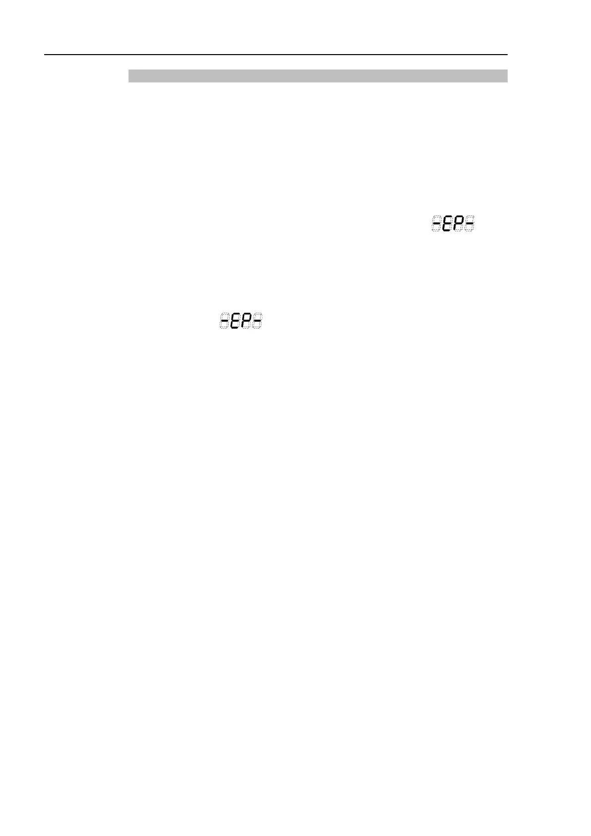
(2) Make sure that the seven-segment LED on the Controller displays .
(3) Make sure that “EStop” is displayed on the EPSON RC+ 7.0 status bar.
(4) Release the Emergency Stop Switch.
(5) Select EPSON RC+ 7.0-[Tools]-[Robot Manager]-[Control Panel] and click the
<Reset> button to execute the RESET command.
(6) Make sure that LED is turned OFF and that “E-Stop” is dimmed on the
main window status bar.
Drive Unit RC700DU
(1) Turn ON the Controller to boot the software while pressing the Emergency Stop
switch.
(2) Make sure that “ERROR/E-STOP” LED on Drive Unit has been turned ON.
(3) Make sure that “EStop” is displayed on the status bar on the EPSON RC+ main
window.
(4) Release the Emergency Stop Switch.
(5) Execute the RESET command.
(6) Make sure that “ERROR/E-STOP” LED turns OFF and “EStop” display fades on the
main window status bar.
 Loading...


