Installation 2. Installation
RC700 Series Rev.3 41
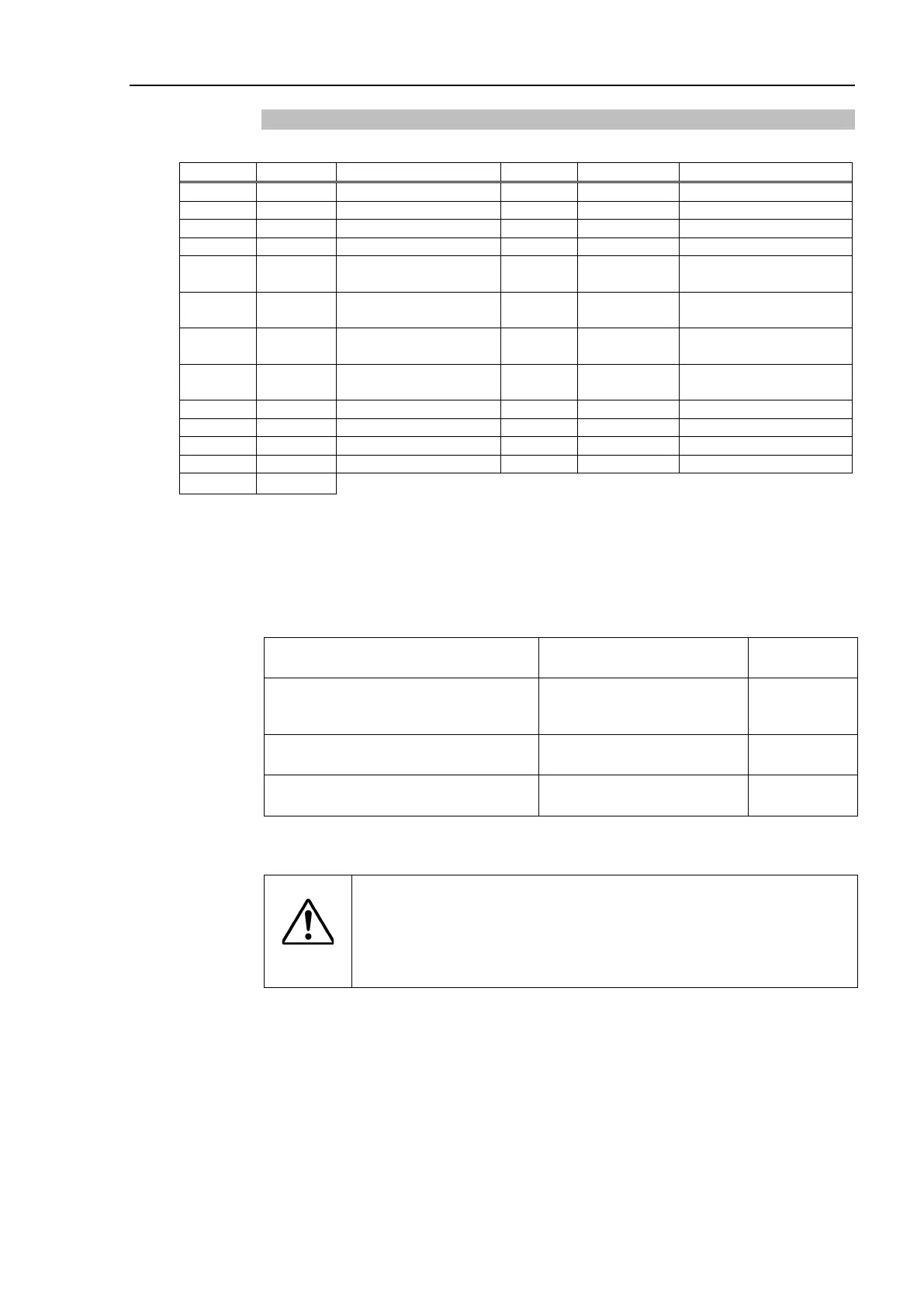
Pin Assignments
The EMERGENCY connector pin ass
ignments are as follows:
5 Not used
Emergency Stop circuit
1 (+)*4
18 SDLATCH1
Emergency Stop circuit 2
(+)*4
6 Not used
Emergency Stop circuit
1 (
−
19 SDLATCH2
Emergency Stop circuit 2
(
−
7 SD11 *1 20 SD21
Safety Door Latch
Release
8 SD12 *1 21 SD22
Safety Door Latch
Release
*1 Do not connect anything to these pins.
*2 A critical error occurs if the input values from the Safety Door 1 and Safety Door 2 are
different for two or more seconds. They must be connected to the same switch with
two sets of contacts.
*3 A critical error occurs if the input values from the Emergency Stop switch contact 1 and
Emergency Stop switch contact 2 are different for two or more seconds. They must
be connected the same switch with two sets of contacts.
*4 Do not apply reverse voltage to the Emergency Stop circuit.
Emergency Stop switch output rated
load
+30 V 0.3 A or under 1-2, 14-15 pin
Emergency Stop rated input voltage
range
Emergency Stop rated input current
+24 V ±10%
37.5 mA ±10% / +24V input
3-4, 16-17 pin
Safety Door rated input voltage range
Safety Door rated input current
10 mA / +24 V input
7-8, 20-21 pin
Latch Release rated input voltage range
Latch Release rated input current
10 mA / +24 V input
18-19 pin
The total electrical resistance of the Emergency Stop switches and their circuit should be 1
Ω or less.
CAUTION
The 24 V output is for emergency stop. Do not use it for other
purposes. Doing so may result in system malfunction.
Do not apply reverse voltage to the
Emergency Stop circuit.
Doing so may result in system malfunction.
 Loading...


