Aligning the Antenna
A
0 – 2.5 V DC
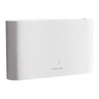
Figure 17 The Position of the Alignment Port
3. Remove the O&M plate from the O&M port.
4. Connect the voltmeter to the alignment port A on the MINI-LINK 6351.
Use the alignment test cable.
7.3.1 Adjusting the Azimuth
1. Adjust the antenna horizontally for maximum alignment value.
Note: Rotate the entire scope of the antenna to find the main lobe. Side
lobes may peak without achieving maximum value.
2. Tighten the locking screws and nuts. Follow the antenna installation
instruction when the maximum value is found.
7.3.2 Adjusting Elevation
1. Adjust the antenna vertically for maximum alignment value.
Note: Rotate the entire scope of the antenna to find the main lobe. Side
lobes may peak without achieving maximum value.
2. Tighten the locking screws and nuts. Follow the antenna installation
instruction when the maximum value is found.
3. Measure the alignment value.
4. Repeat steps Step 1 to Step 3 until you find the maximum alignment value.
5. Record the alignment value.
53
13/1531-HRA 901 17/9 Uen B | 2016-03-04

 Loading...


