Do you have a question about the ESAB Aristo U6 and is the answer not in the manual?
Initial setup menu appears on first power-up. Guides language selection.
Explains the interaction between primary memory and welding data memory for settings.
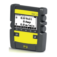
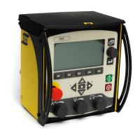
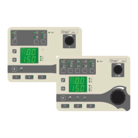
Details the display, knobs, and soft keys of the control panel interface.
Defines symbols used on the display for navigation and parameter adjustment.
Informs about warnings for unsupported functions requiring a software update.
Describes the main menu and the measurements menu functions.
Explains how to navigate to other menus like Process, Settings, Configure, or Memory.
Details parameters like Inductance, Gas pre-flow, Hotstart Time, and Crater Fill Time.
Allows changing language, dimensions, panel enable, and trigger data.
Facilitates storing, recalling, and erasing welding data settings.
Lists settings, their ranges, steps, and default values for MIG/MAG welding.
Details settings for MIG/MAG welding when using the pulsing function.
Explains the 2-stroke control mode for welding torch trigger switch operation.
Explains the 4-stroke control mode for welding torch trigger switch operation.
Describes crater filling to avoid pores and thermal cracking at weld end.
Explains hot start for increased current to reduce poor fusion risk.
Details creep start for feeding wire until contact with the workpiece.
Describes gas purging to flush hoses or measure gas flow.
Explains cold wire feed for feeding wire without energizing the arc.
Facilitates setting welding parameters; mutually exclusive with Synergy.
Explains synergy lines for stable arcs with wire, gas, and voltage relationships.
Refers to 'Standard Synergic Lines' and custom packages.
Shows amperage estimate based on wire feed speed, useful when feed speed is unknown.
Higher inductance for flowing weld, less spatter; lower for harsh sound, stable arc.
Time during which shielding gas flows before the arc is struck.
Delay between wire feed unit braking and power unit shutoff.
Gives small short circuits at weld end to stop wire feed and break contact.
Fine-tunes the electric arc at the start moment of welding, requires Synergy OFF.
Controls time shielding gas flows after the arc is extinguished.
Switches between pre-set welding data alternatives via blowpipe trigger.
Uses Arc Voltage Controlled or Off-The-Arc feeder for the feed unit.
For spot-welding thin metal sheets; activation and setting in SETTINGS MENU.
Higher voltage gives longer arc, hotter/wider weld pool; adjustable in MAIN/SELECT MENU.
Speed of filler wire supply, measured in m/min; adjustable in MAIN/SELECT MENU.
Pulse to ensure no ball forms on wire when welding stops.
Describes TIG welding using a non-melting tungsten electrode and shielding gas.
Lists settings, ranges, steps, and default values for TIG welding.
Details settings for TIG welding when using the pulsing function.
Explains the 2-stroke control mode for TIG welding torch switch.
Explains the 4-stroke control mode for TIG welding torch switch.
Strikes the arc via a spark produced by proximity to the workpiece.
Strikes the arc when the electrode contacts the workpiece and is lifted.
Strikes the arc when the tungsten electrode contacts and is lifted from the workpiece.
Used for flushing gas hoses or measuring gas flow before welding.
Controls time shielding gas flows before the arc is struck.
Current rises slowly to set value, providing gentler heating.
Reduces current slowly to avoid crater cracking at weld end.
Controls time shielding gas flows after the arc is extinguished.
Length of time pulse current is on during a pulse cycle.
Length of time background current flows, contributing to total pulse cycle time.
Lower current value used in pulsed current welding.
Higher current value used in pulsed current welding.
Higher current gives wider/deeper penetration; adjustable in MAIN/SELECT MENU.
Switches between pre-set welding data alternatives via blowpipe trigger.
Sets the minimum current for remote control.
For spot-welding thin metal sheets; activation/setting in SETTINGS MENU.
Lists settings like Hot start, Arc force, Current, and Min current for MMA welding.
Lists settings for Electrode diameter and Voltage for Arc-air gouging.
Behavior of the control panel when a remote control unit is connected.
Lists the available languages for the display panel text.
Allows setting dimensions to Metric or Inch.
Enables setting current/voltage/wire feed via panel or remote control unit.
Automatically saves changed settings when a new data setting is recalled.
Sets max/min values for wirefeed/current/voltage for quality assurance.
Restricts access to menus when activated and a lock code is set.
Lock code configured by authorized ESAB technician using ESAB Software Administration Tool.
Activates the Code Lock function via the CONFIGURE MENU.
Explains how to enter a lock code to access a locked menu.
Ensures open-circuit voltage does not exceed 35V when welding is not active.
Procedure to set and store welding data settings in the primary memory.
Procedure to recall stored welding data settings from memory.
Procedure to delete stored welding data from memory positions.
Explains fault codes indicating equipment faults, shown as symbols.
Lists fault codes by unit type (control panel, power unit, etc.) and voltage supply.
Describes corrective actions for program memory (EPROM) and microprocessor RAM errors.
Details errors for external RAM, 5V supply low, intermediate voltage, and high temperature.
Describes errors for +24V power supply (cooling unit) and low battery voltage.
Details errors for +15V, +13V, -15V, +20V/+60V, +10V, and +24V power supply issues.
Covers wire feed speed voltage errors and communication warnings/errors.
Details errors for messages lost and high open-circuit voltage.
Describes 'Lost contact' errors with wire feed unit or power unit.
Covers incorrect settings in external RAM and memory allocation errors.
Describes transmitter and receiver buffer overflow errors.
Details 'Watchdog' errors and 'Out of wire' errors from the wire feed unit.
Covers stack overflow errors and 'No cooling water flow' warnings.
Describes regulator time error and 'No reply from display unit' errors.
Details 'No gas flow' and 'Incompatible units' errors.
Covers power source software issues and memory management errors.
Details errors related to missing dip/spray synergy lines for pulse welding.
Warns that attempting repairs during warranty voids undertakings.
Diagram showing main circuit board components and connections.
Lists wire types, shielding gases, and wire diameters for MIG/MAG synergy welding.
Lists wire types, shielding gases, and diameters for pulsed MIG/MAG synergy.
Lists electrode types and diameters for MMA welding.
Lists electrode types and diameters for Air arc gouging.
North American synergic line data for MIG/MAG welding.
North American synergic line data for Pulsed MIG/MAG welding.
Details MMA welding electrode diameters in inches.
Details Air arc gouging electrode diameters in inches.
Diagram illustrating menu structure for MIG/MAG welding.
Detailed breakdown of Process, Settings, Config, and Memory menus for MIG/MAG welding.
Diagram of menu structure for MIG/MAG welding with pulsing.
Detailed breakdown of menus for MIG/MAG welding with pulsing.
Diagram illustrating menu structure for TIG welding.
Detailed breakdown of menus for TIG welding.
Diagram of menu structure for TIG welding with pulsing.
Detailed breakdown of menus for TIG welding with pulsing.
Diagram illustrating menu structure for TIG welding with Live-Tig start.
Detailed breakdown of menus for TIG welding with Live-Tig start.
Diagram illustrating menu structure for MMA welding.
Detailed breakdown of menus for MMA welding.
Diagram illustrating menu structure for Air gouging.
Detailed breakdown of menus for Air gouging.
| Brand | ESAB |
|---|---|
| Model | Aristo U6 |
| Category | Control Panel |
| Language | English |