Manual 0463 413 001 POWER SUPPLY INTRODUCTION 5-1
5 POWER SUPPLY INTRODUCTION
5.01. Introduction
Design structure of the power source
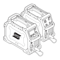
The EMS215ic and EMP215ic power source is operating on the inverter principle. It consists of a number of
function modules. Each module has a module number, which is always included as the first part of the name/
identification of components in the module.
The modules have the following main functions:
• User Interface module - The user interface is a 4.3 inch TFT display with 3 encoders attached to it.
• Power module - Power board includes primary rectifier, pre-charger, main PFC section, auxiliary power
supply, full bridge inverter, main transformer, secondary inductor and secondary diode modules.
• Control module - The control board, with a microprocessor, that monitors and controls the welding pro-
cess.
• Main switch and thermal breaker section (this is connected to enclosure).
5.02. Working Principle
The mains input voltage range is single-phase 120 VAC ±10% and 230 VAC ±10% at rated load.
The primary rectifier, rectifies the input AC voltage. Main PFC section boosts this voltage to 400 VDC with
0.99 power factor.
The main inverter of the power source is a 4-transistor IGBT full bridge, operating at a switching frequency of
47 kHz.
The primary inverter output is connected to a main transformer with an 4:1 turns ratio
The main transformer output is connected to a secondary rectifier which contains four diode modules.














 To Next Page