9-4 DISASSEMBLY Manual 0463 413 001
9.04 Power PCB Assembly Removal
WARNING
Read and follow safety information in Section 1 before proceeding. Follow
anti static precautions when handling any PCB (Printed Circuit Board).
NOTE!
The Control PCB must be removed before you can remove the Power PCB Assembly..
1. First remove the Control PCB by following the previous process.
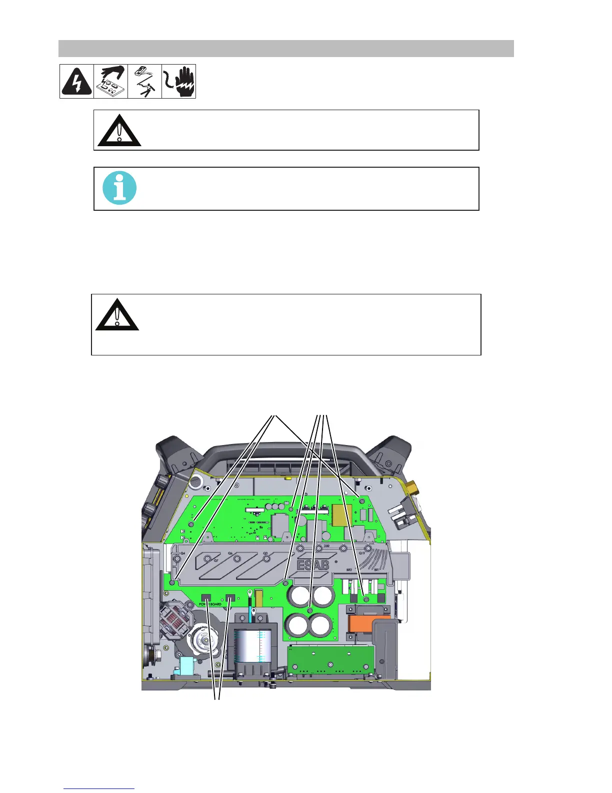
2. Take photos and or notes on all the harness connections along the top and the four (4) transformer and
PFC Inductor connections along the bottom of the Power PCB Assembly.
3. Disconnect each of these from the Power PCB Assembly. (Not shown)
CAUTION
Keep these 4 screws connecting the wires from along the bottom of the board
separate as they are shorter and must be used in the same locations again.
The longer screws from all other locations will damage the board if used re-
connecting these wires.
4. Remove the 9 screws and washers that secure the board to the Center Wall structure. Remove the 4
from the wire spool side first and then the 3 from this side. The 2 screws are for the PFC and are M4x8.
3 4
2 PFC
5. Carefully remove the assembly.
Reverse this process for installation.