6-4 TROUBLESHOOTING Manual 0463 413 001
6.02 Pre Power-up Checks
WARNING
Buss voltage of 400 VDC will be present on the heatsinks of POWER PCB2
while unit is on. Wait 40 seconds after removing power before handling.
Examine unit for any visible signs of damage.
In order to prevent tripping wall fuses and/or causing damage to the unit when power is applied, it is recom-
mended that the following components be checked prior to connecting unit to mains power:
1 MAINS POWER CABLE INPUT POWER CABLE/PLUG
2 SW1 ON/OFF SWITCH
3 CB1 CIRCUIT BREAKER
4 VR1 VARISTOR on POWER PCB2
5 BR1/BR2 BRIDGE RECTIFIERS on POWER PCB2
6 PTC1/RY1 PTC1 (R79) & INRUSH RELAY (RY1) contacts in parallel on POWER
PCB2
7 D49 & D50 DIODES on POWER PCB2
8 Q19 & Q21 PFC TRANSISTORS on POWER PCB2
9 C35-3 WORKING CAPACITORS on POWER PCB2
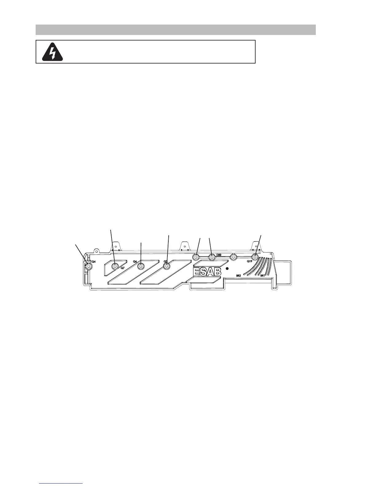
10 Q3,4,6,7 SWITCHING TRANSISTORS on POWER PCB2
Q4 Collector
Q7 Collector
Q6 Collector
Q3 Collector
D49 & D50 Cathode
Q19 Collector
A series of quick checks can be done to verify Main Power components are not shorted. (Remove the right
side panel to access this area.)
Using a meter set to resistance and with the unitSW1 set to ON position:
1. Measure resistance between MAINS CABLE plug blade terminals 1 & 2 for approx.. 1.6K ohms.
Using a meter set to diode test and with the unit SW1 set to ON position:
2. Place positive meter lead on MAINS CABLE blade terminal 1 and negative meter lead on Bridge Recti-
fier BR1 + terminal. Check for forward bias drop (0.3- 0.7v).
3. Place positive meter lead on BR1(+) terminal and negative meter lead on Q4 terminal. Check for forward
bias drop (0.3- 0.7v).
4. Place negative meter lead on terminal Q4 and positive meter lead on Q7 terminal. Check for forward
biased diode (0.3 – 0.7V)
5. Place negative lead on Q7 Terminal and positive probe on BR2(-) terminal. Check for forward bias diode
(0.3 – 0.7v)
6. Place positive meter led on BR2 (-) terminal and negative meter lead on MAINS CABLE plug blade Line
1. Check for forward bias diode (0.3 – 0.7v)