Manual 0463 413 001 TROUBLESHOOTING 6-25
6.06 Test Procedure/troubleshooting
POWER PCB2 - Power Supply Test
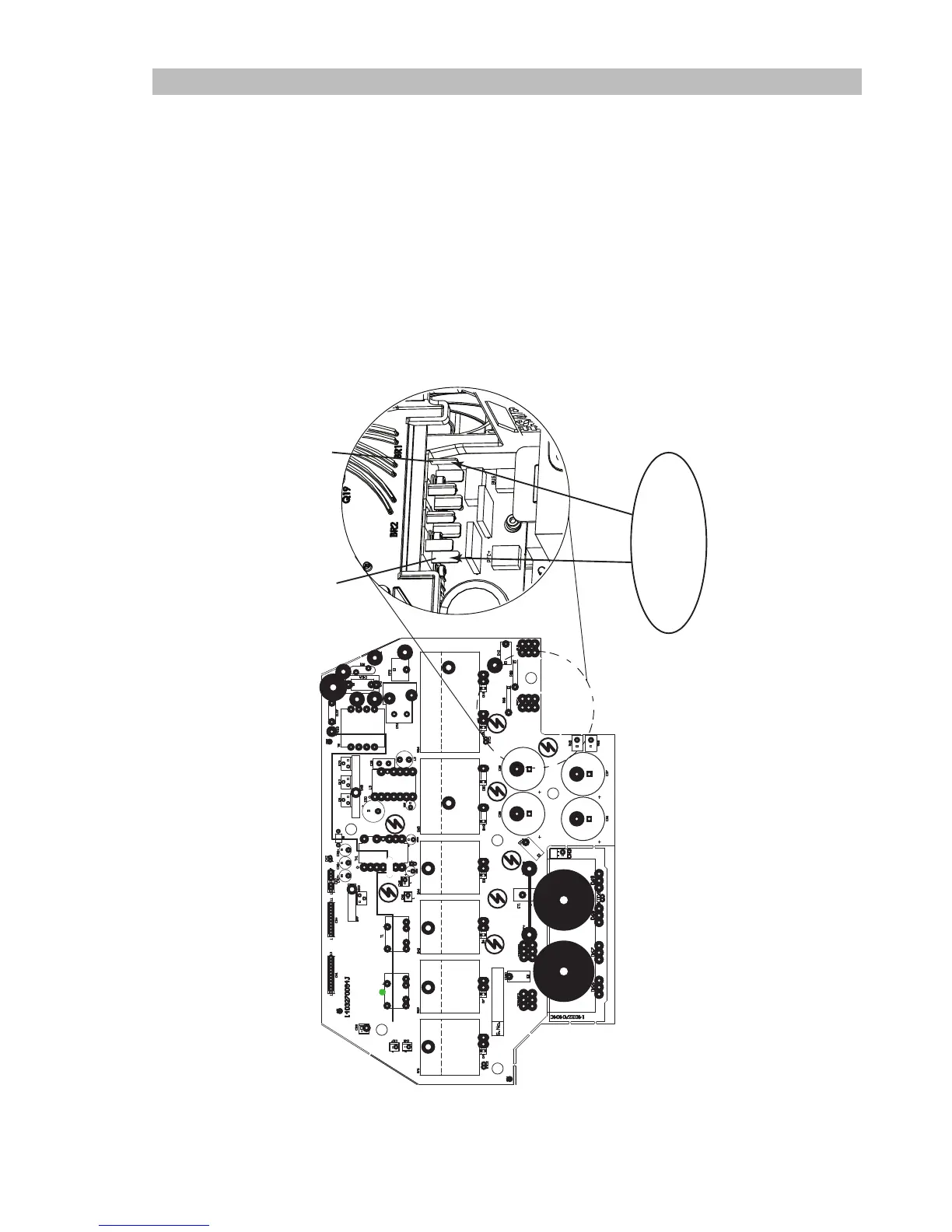
1) Measure for Mains voltage on POWER PCB2 between terminals LINE1 to LINE2.
2) Check LEDs Status
D42 +24V_SEC OK ON
D53 +18VDC_PRI OK ON
3) Measure for 400VDC buss voltage between terminals LINE+ to LINE-.
If problem is found, remove power, disconnect the harness connectors from CONTROL PCB3 connectors CN1,
CN2 and CN4. Retest POWER PCB2.
If findings are still incorrect replace POWER PCB2.
The following image shows the previous steps (1a) listed. In the oval you will see the step number and below
that the meter reading you should see.
1a
120VAC +/- 10%
OR
208/230VAC +/- 10%
BR2(-)
BR1(+)
 Loading...