6-2 TROUBLESHOOTING Manual 0463 413 001
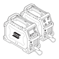
8 Err 008 Critical "VOLTAGE
FAULT
SERVICE
REQUIRED"
Open circuit
Voltage error, OKC
voltage signal not
sensed at Control
Brd CN1 as
expected
UI Display & CN8
Ctrl PCB
We start sensing this voltage only
when weld activity is expected to
be ocurring. If this failure happens
check ctrl connectors CN1 to okc
and CN18 to current sensor for
continuity. Check ctrl pcb for pres-
ence of +/- 15v, D35 is on. If D35 or
either 15V is not to specified values
replace ctrl pcb
ITEM# GRAPHIC
SYMBOL
ERROR
CODE
Serverity Error Mes-
sage on
Display
Functional Circuit
Failure Explanation
Where displayed Possible Cause or Repair Action
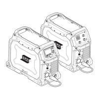
9 Err 009 Warning "LOW
INPUT
"
Low Voltage Error,
ac mains voltage
is less than 108
VAC.
UI Display & CN8
Ctrl PCB
Degrades weld performance, could
trigger Err 003 if severe enough.
Increase input mains line voltage.
Check dc voltage across D55 for
100:1 ratio of ac input voltage. Ex.
118 ac rms input will give 1.18vdc
at D55. If not measured correctly
possible issue is transformer T5 on
power pc faulty or cntrl pcb faulty.
10 N/A Err 010 reserved
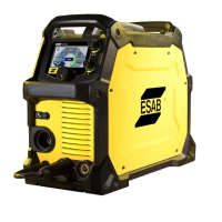
11 Err 011 Critical DEFAULT
RESET UN-
CONFIRMED
**SYSTEM
LOCKED
CYCLE AC
POWER**
User has at-
tempted to
reset parameter
or factory resets
and this was not
confirmed by the
system. Possible
software bug or
communication
protocol error.
UI Display & CN8
Ctrl PCB
Should not experience this error in
the field, Causes are poor communi-
cation with the control (which should
cause err 012), unknown software
bug, UI panel NVRAM not responding
correctly. Check UI panel and control
is latest sw. Test by plugging in a
spare UI panel and perform factory
reset, if fails replace control pcb if
passes replace UI pcb.
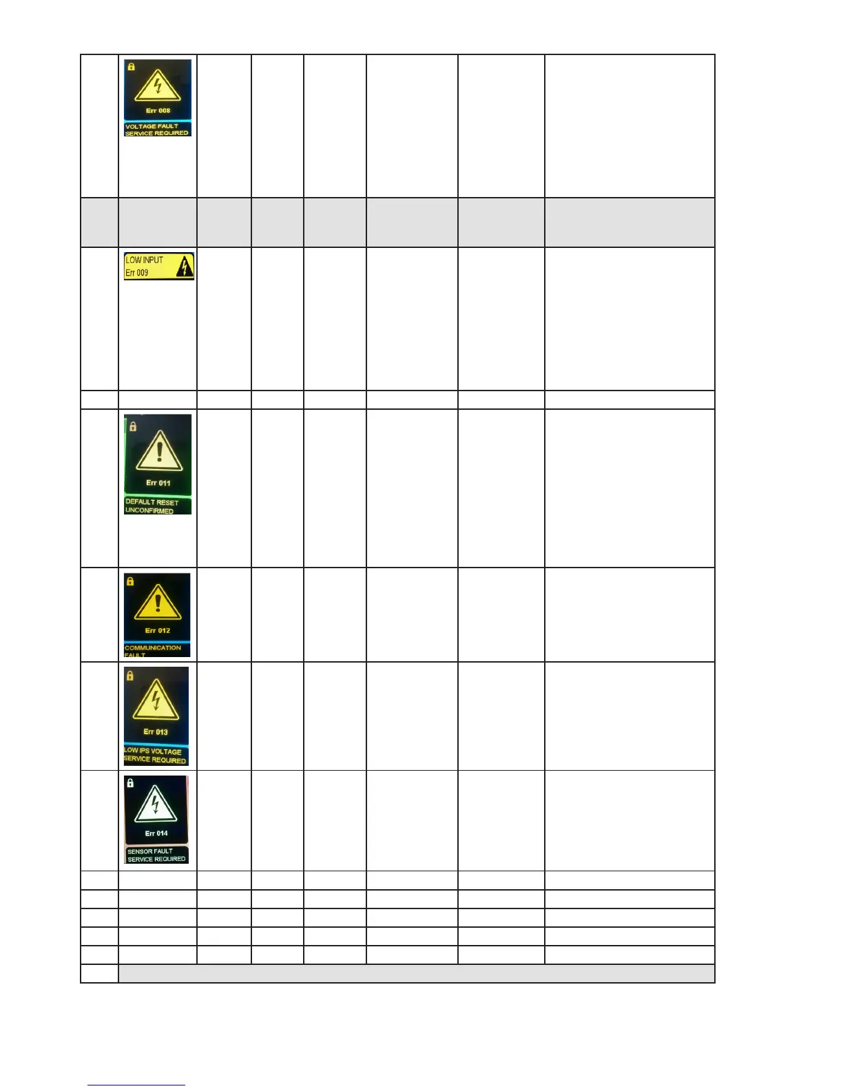
12 Err 012 Critical "COMMU-
NICATION
FAULT "
Communication
Link Down, no
communication
between UI and
Ctrl pcb at CN6
UI Display Possible bad connection at CN6 on
Ctrl pcb, bad conneciton at CN3
UI pcb, bad/broken cable between
these pcbs, or one of these pcbs
are bad.
13 Err 013 Critical LOW IPS
VOLTAGE
DETECTED
Low Internal
Power Supply
(IPS) Voltage Error,
+24V IPS is less
than 22VDC
UI Display & CN8
Ctrl PCB, D40 on
Ctrl PCB
Possible power pcb IPS is bad. Pos-
sible faulty detection ckt on control
pcb. Measure for >23.4 VDC on
both sides of D51 on the control pcb.
Check input source of +24 from the
power pcb
14 Err 014 Critical "SENSOR
FAULT
SERVICE
REQUIRED"
Secondary Current
Sensor CN18
UI Display & CN8
Ctrl PCB
Bad Current Sensor, poor cable con-
nection on Ctrl PCB CN18 or the sen-
sor. Faulty Control PCB - R34 bad.
15 N/A Err 015 reserved
16 N/A Err 016 reserved
17 N/A Err 017 reserved
18 N/A Err 018 reserved
19 N/A Err 019 reserved
ERROR ON UI SIDE Error Level 020 and above