ESAB FABRICATOR 141i
BASIC WELDING GUIDE 4-2 Manual 0-5420
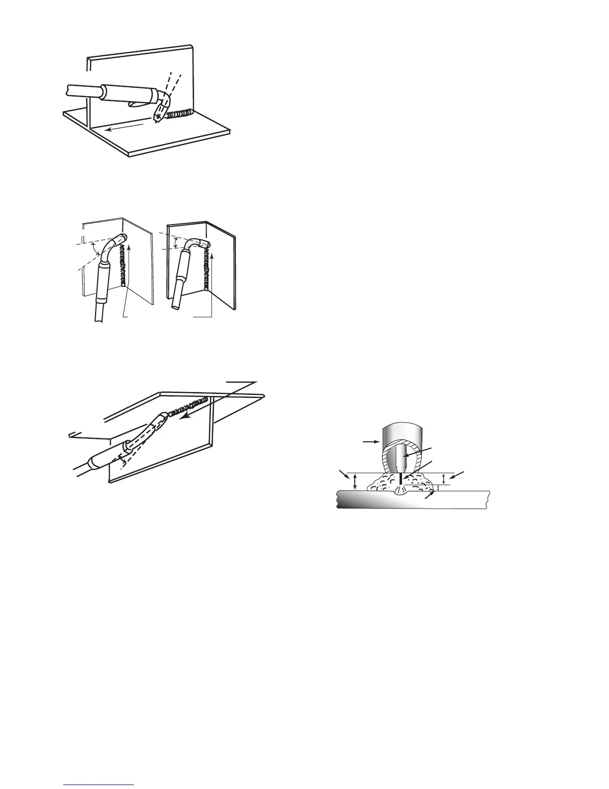
Horizontal Fillet Weld
Direction of
Travel
5° to 15°
Longitudinal Angle
30° to 60°
Transverse Angle
Art # A-08994
Figure 4-5
Vertical Fillet Welds
Art # A-08995
30° to 60°
Transverse
Angle
30° to 60°
Transverse
Angle
Direction of Travel
10°
Longitudinal Angle
Angle
Figure 4-6
Art # A-08996
30° to 60°
Transverse Angle
5° to 15°
Longitudinal
Angle
Figure 4-7
Distance from the MIG Gun Nozzle to the Work Piece
The electrode wire stick-out from the MIG Gun nozzle should
be between 3/8" (10mm) to 3/4" (20.0mm). This distance may
vary depending on the type of joint that is being welded.
Travel Speed
The speed at which the molten pool travels influences the
width of the weld and penetration of the welding run.
MIG Welding Variables
Most of the welding done by all processes is on carbon steel.
The items below describe the welding variables in short-arc
welding of 24 ga. (0.6mm) to ¼” (6.4mm) mild sheet or plate.
The applied techniques and end results in the MIG process are
controlled by these variables.
Preselected Variables
Preselected variables depend upon the type of material being
welded, the thickness of the material, the welding position, the
deposition rate and the mechanical properties. These variables
are:
• Type of electrode wire
• Size of electrode wire
• Type of gas (not applicable to self shielding wires FCAW)
• Gas flow rate (not applicable to self shielding wires
FCAW)
Primary Adjustable Variables
These control the process after preselected variables have
been found. They control the penetration, bead width, bead
height, arc stability, deposition rate and weld soundness. They
are:
• Arc Voltage
• Welding current (wire feed speed)
• Travel speed
Secondary Adjustable Variables
These variables cause changes in primary adjustable variables
which in turn cause the desired change in the bead formation.
They are:
1. Stick-out (distance between the end of the contact
tube (tip) and the end of the electrode wire). Maintain
at about 3/8" (10mm) stick-out
2. Wire Feed Speed. Increase in wire feed speed
increases weld current, Decrease in wire feed speed
decreases weld current.
Art # A-08997_AD
Gas Nozzle
Electrode Wire
Average Arc Length
Electrode Stick-Out
Tip to
Work Distance
Actual Stick-out
Contact Tip (Tube)
Figure 4-8
3. Nozzle Angle. This refers to the position of the welding
MIG Gun in relation to the joint. The transverse angle
is usually one half the included angle between plates
forming the joint. The longitudinal angle is the angle
between the centre line of the welding MIG Gun and a
line perpendicular to the axis of the weld. The longi-
tudinal angle is generally called the Nozzle Angle and
can be either trailing (pulling) or leading (pushing).
Whether the operator is left handed or right handed
has to be considered to realize the effects of each
angle in relation to the direction of travel.
 Loading...