Part 3 SES 2000 AUTOCLAVE
Page 24 of 43 ST-SM8l
PART 3 MAINTENANCE
SPECIAL OPERATING MODES
Demonstration Mode
3.25 Demonstration mode provides a selection of the
available display messages for use at exhibitions and
for customer education in whatever language has been
selected. To enter this mode proceed as follows:
a Switch off power.
b Push and hold the 134°C and 121°C (without
drying) programme buttons and switch on power.
c Release programme buttons when messages
start to appear:
3.26 To exit the demonstration mode, switch off power
to the unit, then switch it on again.
Engineering Mode
CAUTION
Inbuilt protection by the controller is not
operational in Engineering Mode.
3.27 To enter the Engineering Mode proceed as
follows:
a Switch off power.
b Push and hold the 134°C and 121°C ‘with drying’
programme buttons (the bottom two buttons) and
switch on power.
c Release programme buttons when messages
start to appear. The messages, in order are:
8.8.8.8.8. with a continuous audible signal and all
programme selection LED’s illuminated, followed
by ‘count’, then the accumulative number of
completed cycles, then the error code (see section
3.40) for the last error stored in memory and finally
‘Engin’.
Note
In the engineering mode the display will read ‘Engin’
unless the heater is on, in which case the normal
temperature display will show.
3.28 In the Engineering Mode the programme selector
buttons and programme indicator LED’s function as
follows:
a Button 134°C (without drying). Press to check
chamber discharge valve function. If the valve is
working, the valve solenoid will be heard to click.
b Button 121°C (without drying). Press to check
water fill valve function. By opening chamber door
the water can be seen to flow into the chamber.
Note
Only one of the valves can be energised at a time.
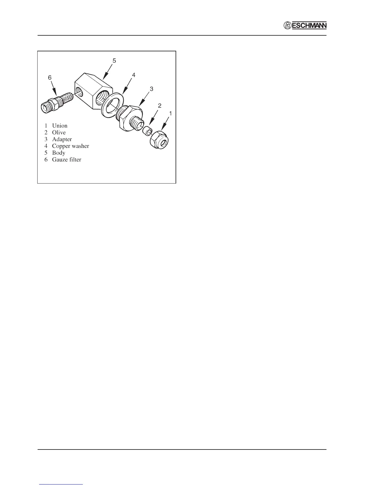
Fig. 6 Filter Unit Disassembly
Discharge Line Filter (Fig. 3 item 10 and Fig. 6)
3.23 The filter in the discharge line should be removed
and cleaned approximately every 12 months as follows:
a Ensure all water has been discharged from
chamber back into the reservoir and switch off
unit.
b Remove filter assembly from discharge line,
disassemble components and rinse clean all parts,
using distilled water only.
c Allow components to dry, then reassemble filter
unit. Ensure that copper washer is correctly
positioned with bevel side of washer against filter
body. If washer is damaged, renew it.
Printer (Fig. 2 item 22)
3.24 Remove the printer as follows:
a Disconnect all electrical connections noting their
position and orientation for correct reconnection.
b Remove two screws from the printer securing
bracket.
c Withdraw the printer through the front panel.
d Refit the printer using the reverse removal
procedure.