SES 2000 AUTOCLAVE Part 2
ST-SM8l Page 7 of 43
PART 2 DESCRIPTION
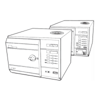
GENERAL (Fig 2)
2.1 The autoclave is a portable steam unit heated by
a single element and can be supplied to suit any of the
mains supplies shown in Technical Data.
2.2 The unit is electronically controlled and offers a
selection of sterilizing programmes as follows:
134°C without the drying phase
121°C without the drying phase
134°C with the drying phase
121°C with the drying phase
For sterilizing pressures and drying times refer to
Technical Data.
2.3 The required sterilizing programme is selected
and started by pressing the appropriate programme
button on the front panel of the unit, following which the
sterilizing/drying cycle proceeds automatically until
complete. If the autoclave has a printer, the printer will
start automatically when the programme button is
pressed.
2.4 Indication of cycle status is provided by a digital
display. If an error should occur during a cycle this also
is indicated by the digital display.
OPERATING FEATURES (Figs 2, 3 and 4)
2.5 The following equipment, designed for control
and/or protection, is incorporated in the autoclave:
Pressure Gauge (Fig. 3 item 3). This is used to
indicate pressure inside chamber.
Process Display Window (Fig. 2 item 1). The
digital display indicates the temperature inside
the chamber and also provides simple messages
for the user which indicate the stages through the
cycle, and also error conditions, should any occur.
Four Programme Selector Buttons (Fig. 4, item
15). These are used to select and start a particular
cycle. They can also be used to place the machine
in the ‘Demonstration’ or ‘Engineering’ mode as
described later.
Green Light Emitting Diodes (LED’s) (Fig. 4 item
16). There are four LED’s and these are used
primarily to indicate the point at which the required
sterilizing cycle can be selected and started and,
when this has been done, to indicate which
particular cycle is in progress.
Power On/Off Switch (Fig. 4 item 17). This switch
controls mains power supply to the unit.
Overheat Warning Lamp (Fig. 4 item 18). The
illumination of this warning lamp indicates that the
protective thermal fuse (Fig. 4 item 7) has operated.
Door Latching Handle (Fig. 2 item 4). This handle
operates the door mechanism to secure the door
in the locked position against the chamber mouth.
Door Secondary Latch (Fig. 2 item 6). This engages
a safety catch to ensure the door does not fly open
should there be residual pressure in the chamber
when the door latching handle is operated. It is
also used to keep the door slightly open during the
drying part of the cycle.
Door Interlock Microswitch (Fig. 4 item 6). This is
used to signal to the controller that the door is
properly closed. It is operated via a simple
adjustable mechanism and should operate just as
the door becomes fully closed.
Pressure Door Lock (Fig. 3 item 7). This is a safety
device designed to ensure that the door cannot be
opened if the internal chamber pressure exceeds
approximately 0.2 bar (3.0 lbf/in
2
). The device
comprises a spring-loaded plunger driven by the
chamber pressure via a rubber diaphragm.
Solenoid Door Lock (Fig. 4 item 22) ‘CE ONLY’
see note page 38. This lock prevents the door
being opened by the operator, once the cycle has
been started. The lock holds the door closed until
the sterilizing cycle is complete. It will also keep
the door closed under all fault conditions. As
absence of power to the unit constitutes a ‘fault’
this also means that the unit power switch must be
switched ‘on’ in order to open the door.
Note: If it is necessary to override the electrical door
lock to clear an error code, this is done by switching off
the power switch then, after a few seconds, switching
it back on again while pressing and holding any one of
the programme selector buttons on the front panel.
Water Reservoir (Fig. 2 item 17). This is used to
hold distilled, deionized, or purified water before
being admitted to the chamber via the water fill
valve, and to receive the hot water and steam
vapour emitted from the chamber towards the end
of the cycle, via the discharge valve.
Heating Element (Fig. 4 item 1). This consists of
a single immersion element inside the chamber. It
is controlled via the solid state relay and heater
thermostat. Refer to the Technical Data for heater
element loading.
Solid State Relay (Fig. 4 item 8) 'Non-CE Units' see
note page 38. This is switched on and off by the
controller as necessary and is the means of controlling
the heater output. The solid state relay is fitted on the
protection relay printed circuit board which is mounted
on the internal bulkhead and is rated at 25A, 400V
(repetitive reverse blocking voltage) or such as to be
suitable for use on a 230V a.c. supply.
Solid State Relay (Fig. 4 item 8A) ‘CE ONLY’ see
note page 38. On CE units the Solid state relay is
fitted on the relay protection board.
Mechanical Relay (Fig 4 item 21) ‘CE ONLY’ see
note page 38. This relay isolates the heater circuit