SES 2000 AUTOCLAVE Part 3
ST-SM8l Page 25 of 43
PART 3 MAINTENANCE
c (CE ONLY see note page 38) Button 134°C (with
drying). Press to check the solenoid lock retracts.
d Button 121°C (with drying). To switch on heater,
press and hold in this button until ‘HEAt’ or (if hot)
temperature display appears, then release. To
switch off heater, press and hold in this button
again until ‘Engin’ display appears, then release it.
CAUTION
The thermal fuse will ‘blow’ if the heater
is left switched on and the cycling
thermostat is faulty.
e Programme ‘134°C without drying’ LED will
illuminate if door switch closes.
f Programme ‘134°C with drying’ LED will illuminate
if chamber water level sensor is immersed.
Note: This condition can be simulated as follows. With
the door open and furniture removed check that
LED is not illuminated. Then using a long screw
driver, short the chamber level sensor to ground
(the chamber wall) and check that the LED
illuminates.
3.29 To exit Engineering Mode, switch off power to the
unit, then switch it on again.
Set-Up Mode
3.30 The set-up procedure will only have to be done
if the printer interface board is changed. Once started,
the procedure must be completed in full, do not switch-
off the power before it has been completed. If a mistake
is made, switch-off the power, and start again. On
autoclaves fitted with a printer, a printout showing the
main items selected within the set-up procedure will be
printed when the procedure has been completed.
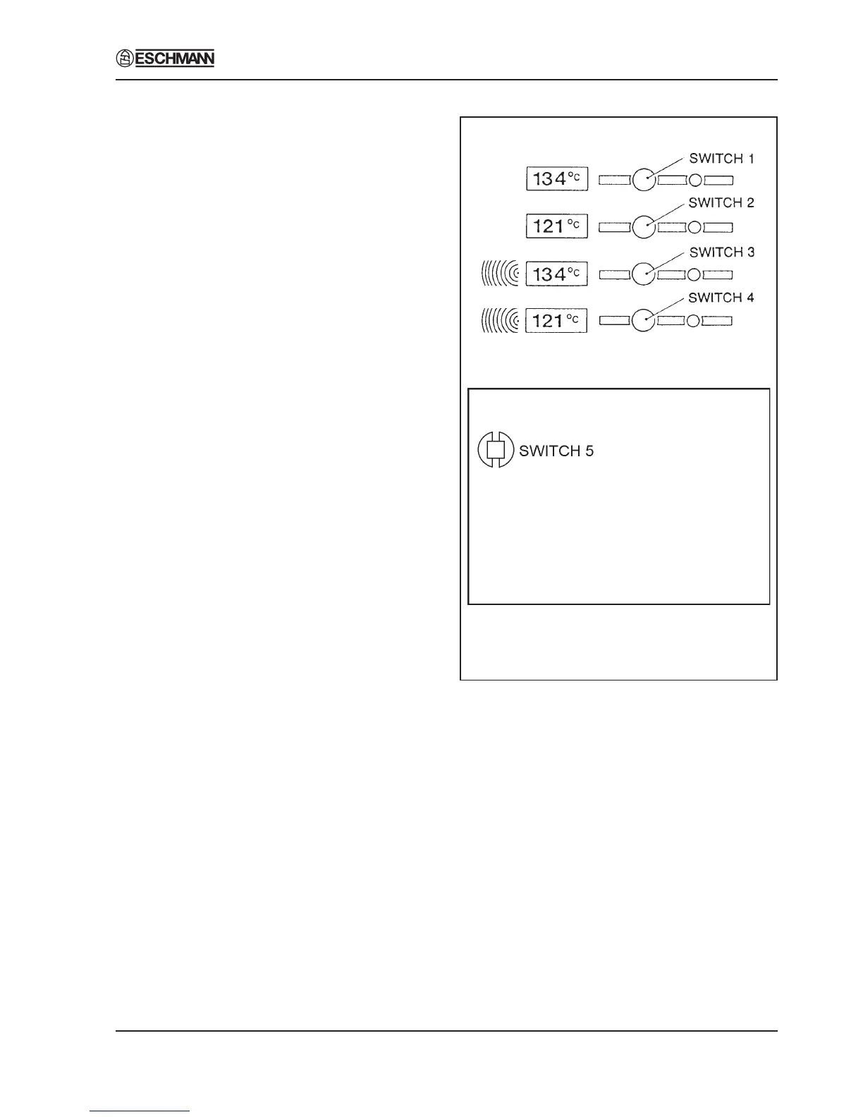
Switch Identities and Functions (Fig. 7)
3.31 Throughout the set-up procedure, the following
switches are used, and they have the following identities
and functions:
Switch 1 (SW1) Indicates ‘yes’ or ‘up’.
Switch 2 (SW2) Indicates ‘no’ or ‘down’.
Switch 3 (SW3) Indicates ‘accept’.
Switch 5 (SW5) Initiates the set-up mode, and is
fitted in the top left-hand corner of
the controller board.
Autoclave Front Panel
Controller Board
Fig. 7 Switch Identities and Functions
Power-On Modes
3.32 The following switches, ‘held-pressed’ when
power is switched-on, will initiate their associated
modes:
Switch 5 Set-Up Mode.
Switches 3 and 4 Engineering Mode
Switches 2 and 3 Calibration Mode
Switches 1 and 2 Demonstration Mode.
Switches 1 and 4 Clock-Set Mode.
Note
When setting the clock (to change from BST to GMT for
example) use the switch 1 and 4 combination, not the
set-up procedure.