8-1-2-3 Replacement of left side motor drive board assy
Follow the procedures of the right side motor drive board assy.
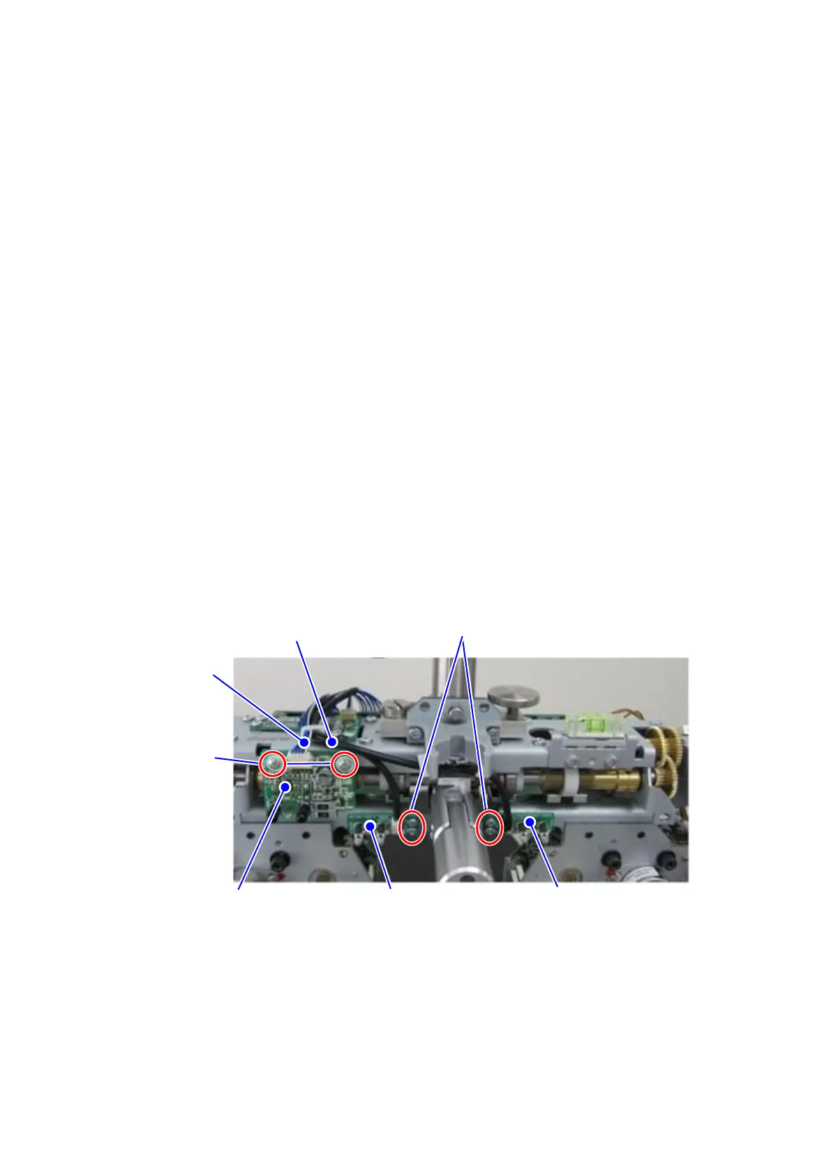
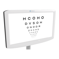
8-1-3 Replacement of infrared communication board assy, LED board
assy for lighting right side near point chart, LED board assy for
lighting left side near point chart, head peripheral harness and
infrared harness
1) Remove the PD case F and B (refer to 8-1-1).
2) Remove and replace all of the harnesses connected to 2 board fixing screws 1 at the time
of replacing the infrared communication board assy.
(Do not loose the spacer between the board and the plate when unscrewing the 2 board
fixing screws 1.)
3) Remove and replace all of the harnesses connected to 2 board fixing screws 2 at the time
of replacing the LED board assy for lighting the right side near point chart.
4) Remove it by the procedures same with 3) above at the time of replacing the LED board
assy for lighting the left side near point chart.
5) Remove and replace all of the connectors connected when replacing the head peripheral
harness and the infrared harness.
Reassemble it with the opposite procedures of the disassembling.
Infrared communication
board assy
Board assy for lighting left
side near point chart
Board assy for
lighting right side
near point chart