Do you have a question about the EST Encon Evolution and is the answer not in the manual?
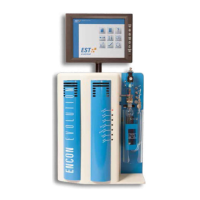
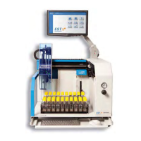
Overview of the Encon Evolution's features, capabilities, and technological advancements.
Detailed technical specifications including features, dimensions, weight, and operating ranges.
Identifies important safety warnings, symbols, and their meanings for safe operation.
Guidelines for proper disposal and recycling of the product according to regulations.
Provides general guidance and critical notes for system installation and setup.
Specifies the necessary dimensions, ventilation, and weight considerations for the installation area.
Outlines the electrical voltage, current, and circuit breaker specifications for the unit.
Instructions for connecting the Encon Evolution to a Gas Chromatograph.
Details on how to connect the monitor to the instrument.
Instructions for connecting the mouse to the instrument's USB port.
Procedures for connecting pressurization and carrier gas lines.
Guide for plugging in the power cord and ensuring proper grounding.
Procedures for turning on the Encon Evolution and initiating the system.
Steps to safely power on the Encon Evolution and prepare for operation.
Instructions for launching the Encon EV software and logging in.
Proper procedure for shutting down the Encon EV and its operating system.
Displays instrument name, serial number, and software version for identification.
Configuring instrument settings like GC interface, gas type, and trap maintenance.
Configuring GC interface signals (TTL Low, TTL High, CC Open).
Configuring GC interface signals (CC Closure).
Selecting the type of gas (Helium or Nitrogen) used by the instrument.
Setting up communication modes (Remote and Local) for I/O.
Selecting the type of trap installed in the Encon EV.
Setting the maximum temperature for the purge ready signal.
Programming reminders for trap replacement.
Managing user accounts and access levels for the Encon EV.
Defines user access levels, configured by a Field Service Engineer.
Setting parameters for the concentrator's operation.
Protects against flooding if sample fails to drain from the previous run.
Detects foam in glassware, initiating a drain and blank run.
Performs automated leak checks before method runs or sequence lines.
Conserves energy and gas during idle instrument time.
Sets the adsorbent trap temperature before purge ready status.
Sets the MoRT tube temperature before purge ready status.
Sets the rate of purge gas flow through the sample pathway.
Enables changing purge flow rates dynamically during the purge cycle.
Defines the total length of time for the sample purge.
Sets the adsorbent trap temperature during dry purge.
Sets the rate of pressurization gas during the dry purge process.
Defines the total length of time for the dry purge.
Equilibriates system pressure to GC head pressure before desorb preheat.
Enhanced feature for lower trap flow during desorb, maintaining higher split ratios.
Heats adsorbent trap before GC carrier gas transfer to GC inlet.
Sets the temperature the adsorbent trap maintains during the desorb process.
Sets the duration GC carrier gas is in line with the trap for analyte transfer.
Sets the temperature of the adsorbent trap during bake.
Enables programming of ramp settings for trap bake temperature.
Sets the temperature for the MoRT tube during bake.
Sets the flow rate of pressurization gas during the bake cycle.
Enables changing bake flow rates during the dry purge cycle.
Defines the total length of time for one bake cycle.
Sets the number of bake cycles for one sample analysis.
Enables or disables the sample heater during the bake cycle.
Allows navigation through the purge and trap process steps.
Starts or stops the selected Purge & Trap method.
Pauses the current operation and displays a timer.
Displays the real-time status and remaining time of the current function.
Indicates the readiness status of the connected Gas Chromatograph.
Instructions for updating the Encon EV software via ZIP or EXE archives.
Critical safety steps (power off, disconnect, cool down) before servicing the instrument.
Explains the function of various icons within the Diagnostics screen.
Manually adjusting temperatures for heated zones like Trap, MoRT, and Transfer Line.
Manually actuating solenoid valves to control gas flow pathways.
Selecting and visualizing different flow pathways for instrument operation.
Performing leak checks and flow checks to ensure proper system operation.
Calibrating flow rates to ensure accurate measurements and performance.
Performing manual bake cycles for the trap and/or MoRT tube.
Accessing calibration functions for flow, heaters, valves, and digital I/O.
Manually draining the sparge vessel, optionally with a bake cycle.
Instructions for manually injecting samples directly onto the instrument's trap.
| Model | Encon Evolution |
|---|---|
| Manufacturer | EST |
| Category | Laboratory Equipment |
| Dimensions | Varies by model - consult manufacturer's specifications |
| Weight | Varies by model - consult manufacturer's specifications |
| Operating Temperature | -10°C to 60°C (Specific range varies by model) |
| Storage Temperature | 0°C to 40°C |
| Humidity Range | 10% to 95% RH (Non-condensing, specific range varies by model) |
| Equipment Type | Environmental Chamber |