24
Wiring diagram LokSoundInstalling the decoder
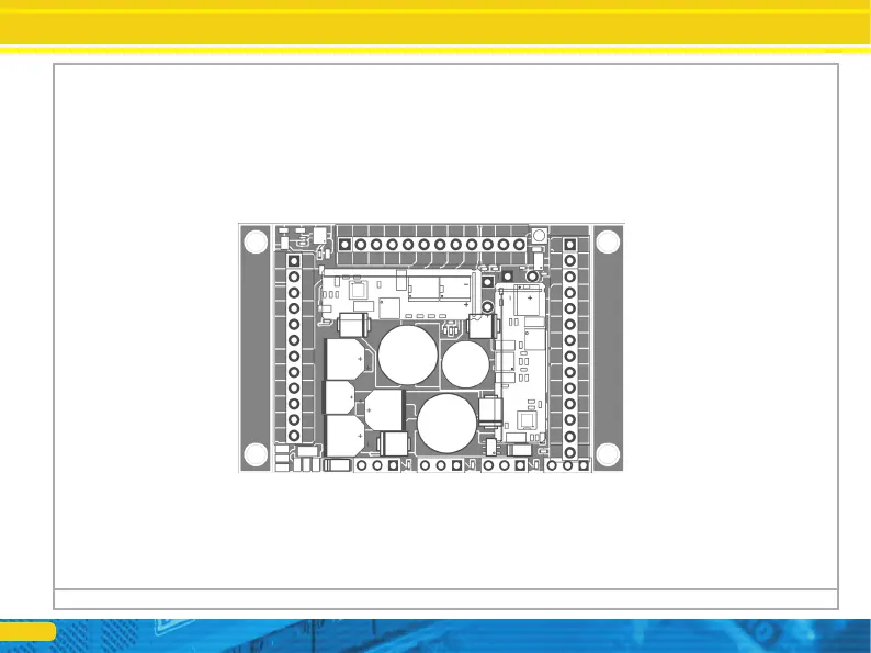
Figure 8: LokSound XL 5 pin connector - allocation
58515 LokSound XL 5 "pin header" 68513
LokSound XL 5 "screw"
Siding left --------------- --------------- right
track connection right track connection
(alternative) ----------- -----
Motor connection right ----------------
U + (positive pole) --------------- + U
(positive pole) ----------------
GND ----------------
Motor Connection left ----------------
wheel sensor ----------------
Left motor terminal (alternate) ----------------
Speaker 1 # 1 --------------- Speaker 1
# 2 ----------------
---------- - ----- AUX11 / Susi Dta / Servo5 (Only header)
---------- - ----Rear light -
---------- - ----- light front
---------- - ----- Sensor input 1
---------- - ----- AUX1 (Power)
---------- - ----- AUX2 (Power)
---------- - ----- AUX 3 (Power)
---------- - ----- Sensor input 2
---------- - ----- AUX4 (Power)
---------- - ----- AUX5 (Power)
---------- - ----- Auxiliary Board Power Control (Reserved)
---------- - ----- AUX6 (Power)
---------- - ----- U + (+ pole)
---------- - ----- AUX12 / Susi Clk / Servo6 (Only header)
Servo1
Servo2 Servo3 Servo4
GND GND ----------------
----------------
Speaker 1 Volume ----------------
-------- AUX13 (logic levels)
-------- Speakers 2 # 1
-------- Speakers 2 # 2
-------- + 10V
-------- + 5V
-------- AUX7 (Power)
-------- AUX8 (Power)
-------- AUX9 (Power)
-------- AUX10 (Power)
-------- AUX11 / Susi Dta / Servo5
-------- AUX12 / Susi Clk / Servo6
-------- Uvar
GND
+ 5V
IMP
GND
+ 5V
IMP
GND
+ 5V
IMP
GND
IMP +
5V
GND
GND
Speaker 2 Volume