30
Installing the decoder
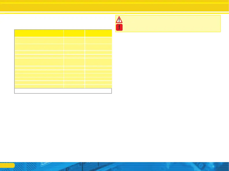
Figure 17: Märklin® cable colors differently to DCC cable colors
after successfully connecting Please measure all connections with an ohm
meter to again. Search in particular nena-circuits to short circuits between the
motor and the rail.
• The red cable is connected telschleifer to the right rail pickup or the co.
• The black cable is connected to the left rail or Gehäu- semasse.
• The orange wire is connected to the motor terminal that was previously
connected to the right wheel (center pick up in AC models).
• The gray cable is connected to the motor terminal that was originally connected
to the left rail (housing mass in AC models).
6.8.5.1. Runs DC and coreless motors
It can be used all conventional reindeer for model trains Gleichstrommoto- if
their current consumption do not exceed the permissible values of the decoder.
it may be klin® In some cases with a 5-pole High Performance Drive by fairy
tale that capacitors directly to the engine a total of 3 RFI suppression are
available.
guide the two capacitors connected directly to the motor and the motor housing
MUST be removed (see Figure 22 on page 33).
6.8.5.2. Connecting Universal Motors with HAMO-Conversions
The built in many older Märklin® locomotives (also known as AC motor known)
can not be connected directly to sound decoders. Previously, these engines
have to with the help of a permanent magnet (so-called "HAMO." - magnetic) to
be converted into a direct current motor. These magnets are available from your
ESU dealer. We provide four different magnets. Please refer to chapter 19.2.
magnet for more information on engine conversions with permanent.
6.8.4. Märklin® cable colors
Märklin® used by DCC color scheme different cable colors. Fig. 17 gives
information.
designation Märklin® color ESU color
(NMRA DCC standard)
AC: center conductor DC:
Right track
red red
AC: Outside (rail) DC: rail links
brown black
Left motor terminal blue orange
Motor output Right green Gray
DC rectified track voltage (+ Pole for functions)
orange blue
Rear output light yellow yellow
Output light Front Gray White
AUX1 brown / red green
output AUX2 Brown Green violet
output AUX3 brown / yellow -
output AUX4 brown / white -
6.8.5. Motor and Track Connections
First disconnect all wires installed in the locomotive and watch out for a
connection via the chassis ground: The two motor connections must be
potential-free, so do not have any connection to the chassis / or the wheels /
current collectors. Especially in Fleischmann® locomotives they are seen
repeatedly exceeded.
Make a note of which motor connection to the right and who was connected to
the left wheel pick. This saves you the connection of the decoder attempts which
cable of the decoder must be connected to which motor connection soldered to
set the correct direction of travel.