27
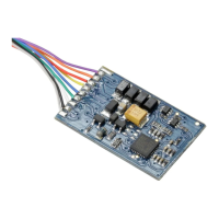
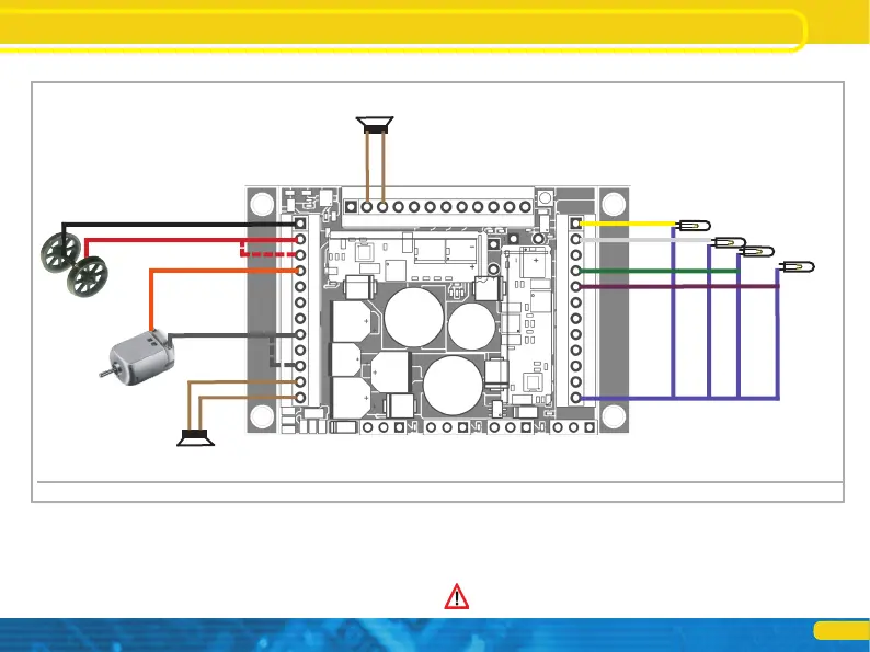
Wiring diagram LokSound 5 XL
Figure 12: Wiring pattern 5 LokSound XL (Example wiring)
6.8.3. Wiring diagram LokSound XL decoders 5
DC motor
Motor output left engine
output right
Speaker 1 4 ~ 16
ohms
6.8.3.1. Following LGB Gear
With the LGB interface cable, the receiver can be connected directly to the
appropriate LGB locomotives. It can of installing the Mo and light functions are
controlled. The cable is available under item number 55026 in the LGB
assortment. Remove the Falststecker the interface cable and screw the
(Stripped) ends in the terminals of the decoder. Set the DIP switches on the
interface according to LGB manual.
Non-compliance can lead to the destruction of the decoder!
Left track connection right
track connection
Right track connection (alternative)
U + (+ pole) +
U (+ pole)
GND
wheel sensor
Speaker 2 (4 ~ 16 ohms)
Light rear light
front
SENSOR1
AUX1 AUX2
AUX3
SENSOR2
AUX4 AUX5
AUX6 U + OFF
(reserved)
Servo1
Servo2 Servo3 Servo4
Speaker 1
Speaker 1
AUX13 logic
levels)
+ 10V
+ 5V AUX7 AUX8 AUX9 AUX10
AUX11 / Susi Dta / Servo5
AUX12 / Susi Clk / Servo6 Uvar
GND
+ 5V
IMP
GND
+ 5V
IMP
GND
+ 5V
IMP
GND
+ 5V
IMP