ES581.4 - User’s Guide16
Hardware Description ETAS
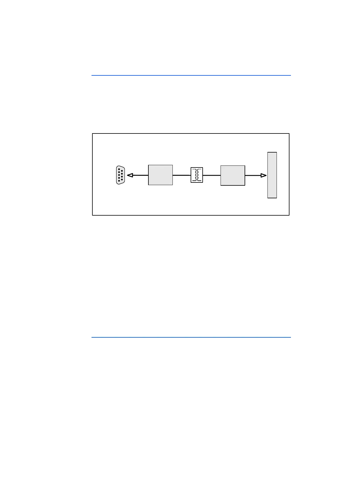
2.6 Block Diagram
The block diagram of the ES581.4 CAN Bus Interface USB Module is shown in
Fig. 2-2.
The ES581.4 is a compact USB module which fits into a standard USB2.0 or
USB1.1 slot. The two independent CAN interfaces of the ES581.4 establish an
easy and direct connection between the PC and the CAN network. Data is
exchanged with the PC via the USB interface.
Fig. 2-2 ES581.4 Block Diagram
CAN signals are transferred to a microcontroller by the CAN transceiver inside
the ES581.4. Upon receipt of a CAN message, the CAN microcontroller time-
stamps and sends the message to the PC across USB. The reverse steps are taken
when the PC application is sending messages to the CAN bus. The microcontrol-
ler is capable of accommodating on an average of 96% bus load up to
500 kBaud rate. The ES581.4 electrically isolates the CAN connection from the
PC to protect the connected devices from damages that may occur due to poten-
tial differences and to avoid any communication drop outs.
Compared to low-cost diagnostic J2534 devices, the ES581.4 is superior in terms
of supported baud rates. Two J2534 applications can access both the channels
of the same device. J2534 devices are limited by their specifications to
500 kBaud and a driver which is optimized for measurement and calibration pur-
poses.
2.7 LEDs
The ES581.4 is equipped with two LEDs to display the operating state of the
module and with one LED to display the function of both CAN interfaces CAN1
and CAN2:
• LED "ON": operating state of the module
• LED "ER": error or firmware update states of the module
• LED "CAN": communication states of the CAN interfaces
ES581.4
USBInterface
Micro‐
controller
CAN1
CAN2
CAN
Transceiver