ES581.4 - User’s Guide36
Technical Data ETAS
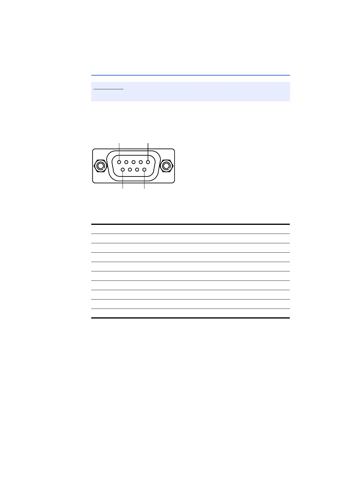
5.4 Pin Assignment
The CAN bus is connected to the ES581.4 CAN Bus Interface USB Module by the
9-pin DSUB connector (see Fig. 5-2).
Fig. 5-2 ES581.4
DSUB Connector
A 9-pin DSUB plug is connected to the "CAN1/ CAN2" socket.
All connections are represented with view onto the interfaces of the module.
Pin Signal Meaning
1 Trigger Pin Not connected
2 CAN 1 Low CAN 1 Low
3 GND Ground
4 CAN 2 Low CAN 2 Low
5 GND (Shield) Ground (Shield)
6 GND Ground
7 CAN 1 High CAN 1 High
8 CAN 2 High CAN 2 High
9 Not connected Not connected