ES581.4 - User’s Guide28
Getting Started ETAS
3.5 USB Connection
After the drivers have been installed, the ES581.4 can be plugged into the PC.
Windows should recognize the device and install the proper drivers for the unit.
Windows informational balloons should appear in the Start bar. Fig. 3-2
on page 28 shows the balloons that appear.
Fig. 3-2 Windows informational ballon
3.6 CAN Connection
The next thing to setup is the connection on the CAN side of the unit.
The ES581.4 connects to the CAN network with standard pinout of the DSUB
connector. The pin assignment for the 9 pin DSUB connector can be found on
the label of the unit and in chapter 5.4 on page 36.
3.6.1 Minimum CAN Connections
The minimum connections needed for connecting to a CAN network are:
• Pin 2 CAN Low
• Pin 7 CAN High
• Pin 6 or Pin 3 GND (either pin will work)
The ground (GND) connection needs to be the same ground as the other CAN
nodes on the bus.
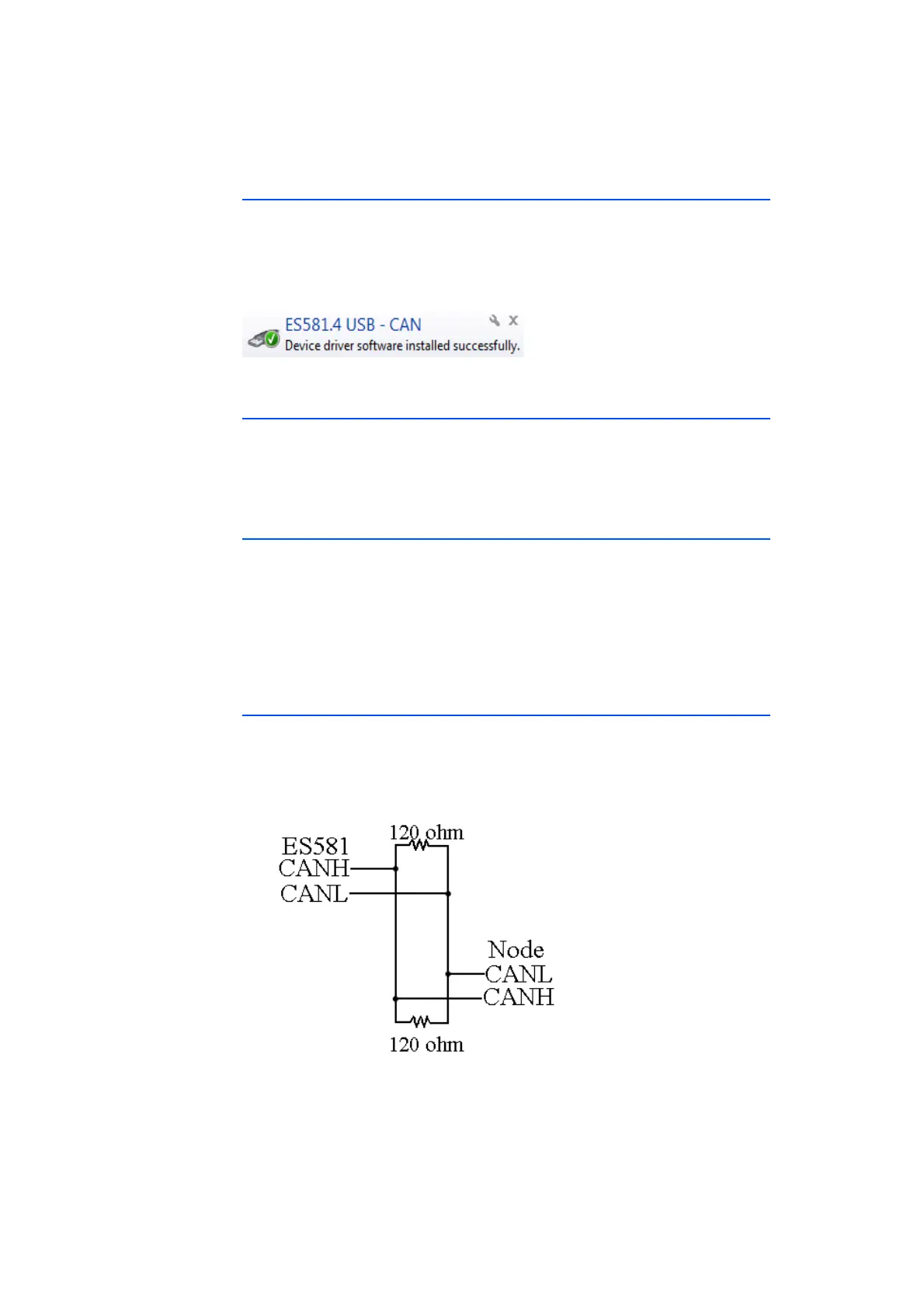
3.6.2 CAN Network Termination
The next thing to connect, if needed, is termination to the CAN network. Nor-
mally a 120 ohm resistor is added to each end of the network. Fig. 3-3
on page 28 shows a simple diagram. Some CAN networks are already termi-
nated, for example in a vehicle, and extra termination is not needed.
Fig. 3-3 CAN Network