EasyManua.ls Logo

evertz HDSD9545DLY-PRO - User Manual

evertz HDSD9545DLY-PRO
64 pages
Print Icon
To Next Page IconTo Next Page
Loading...
HDSD9545DLY-PRO
Profanity Bypass Delay System
Instruction Manual
© Copyright 2004 - 2011
EVERTZ MICROSYSTEMS LTD.
5292 John Lucas Drive,
Burlington, Ontario,
Canada,
L7L 5Z9
Phone: 905-335-3700
Sales Fax: 905-335-3573
Service Fax: 905-335-7571
Internet: Sales: sales@evertz.com
Tech Support: service@evertz.com
Web Page: http://www.evertz.com
Version 1.3.7, February 2011
The material contained in this manual consists of information that is the property of Evertz Microsystems and is intended solely for
the use of purchasers of the Profanity Bypass Delay System. Evertz Microsystems expressly prohibits the use of this manual for
any purpose other than the operation of these units.
All rights reserved. No part of this publication may be reproduced without the express written permission of Evertz Microsystems
Ltd. Copies of this guide can be ordered from your Evertz products dealer or from Evertz Microsystems.

Table of Contents

Question and Answer IconNeed help?

Do you have a question about the evertz HDSD9545DLY-PRO and is the answer not in the manual?

Overview

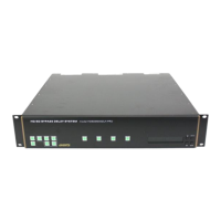
The Evertz HDSD9545DLY-PRO is a Profanity Bypass Delay System designed for live broadcast environments to give operators complete control over program content and eliminate the risk of offensive material being broadcast. It achieves this by introducing a time delay in the program feed, allowing an operator to react to and bypass undesirable content before it reaches viewers.

Function Description:

The core function of the HDSD9545DLY-PRO is to provide a time delay for both video and audio signals, enabling a "clean switch" to an alternative, "safe" feed when offensive material is detected. The system operates with two program paths, both HD and SD compatible. The main program feed typically focuses on the detailed live action, while a secondary backup path usually offers a wide-angle shot or other suitable alternative content. Both channels are delayed by the same amount of time. If an offensive event occurs, the operator can activate a remote button to switch the program video and audio output to the alternative backup channel. Once the offensive material has passed, the output can be seamlessly returned to the main detailed image without the audience noticing an edit.

The device includes a built-in HD/SD quad split output for monitoring, displaying four pictures simultaneously: Program, Delayed Program, Safe, and Delayed Safe. This allows for comprehensive visual monitoring of all feeds. The system is designed with solid-state delay memory, eliminating the need for hard drives and enhancing reliability.

Important Technical Specifications:

  • Video Compatibility: HD or SD SDI compatible, supporting SMPTE 292M (1.5 Gb/s) and SMPTE 259M (270Mb/s) video signals.
  • Delay Capacity:
    • Standard Unit: Up to 24 seconds for HDTV or SDTV, typically allocated as 12 seconds for primary and 12 seconds for secondary paths.
    • With -HD40 Option: Up to 40 seconds for HDTV or 240 seconds for SDTV.
  • Audio Support: Embedded Audio and Discrete (4ch AES) Audio Support.
  • Video Inputs:
    • INPUT A (Program): BNC connector for live program signal, HD or SD serial digital component video (SMPTE 259M-C and SMPTE 292M). Protected by a bypass relay to OUTPUT A.
    • INPUT B (Safe): BNC connector for safe program signal, HD or SD serial digital component video (SMPTE 259M-C and SMPTE 292M).
  • Video Outputs: Five serial digital component video outputs (OUTPUT A, B, C, D, E). OUTPUT A is typically the 'on-air' program video output, protected by a bypass relay to INPUT A. Outputs B, C, D, E are configurable for various feeds, including Delayed Program, Delayed Safe, and quad split.
  • Video Reference: BNC input for analog Genlock reference (tri-level sync, NTSC). Jumper J20 selects 75 ohm termination or high impedance.
  • AES Audio Inputs: Four sets of 4 BNC connectors for AES audio pairs (AES 1-4 INPUT A for program audio, AES 1-4 INPUT B for safe audio). INPUT A audio inputs are protected by bypass relays to AES OUTPUT A.
  • AES Audio Outputs: Four sets of 4 BNC connectors (AES 1-4 OUTPUT A, B, C). AES OUTPUT A is for 'on-air' program audio, protected by bypass relays to AES INPUT A. Outputs B and C are for alternate audio feeds.
  • GPI Control Port: Female DB-25 pin connector providing 8 General Purpose Opto-isolated inputs (GPIs) and 4 General Purpose isolated relay outputs (GPOs). GPIs are active low and can be powered internally (+5V from Vint) or externally (Vext). GPOs are relay contacts, de-energized when power is off.
  • Remote Control Port: 9-pin female D connector for RS-232 serial interface, used for firmware updates. Wired as an RS232 DCE port.
  • Ethernet Network Connection: RJ-45 connector for 10Base-T (10 Mbps) or 100Base-TX (100 Mbps) Fast Ethernet, used for FTP firmware upgrades.
  • Power Requirements: 100 to 240 Volts AC, 50/60 Hz, universal power supplies (auto-sensing input voltage). Minimum 18 AWG power cord. Optional dual power supplies.
  • Electrical Specifications: 40 watts power consumption, TüV Listed, complies with FCC Part 15 Class A and EU EMC directives.
  • Physical Dimensions: 19" W x 3.5" H x 7.75" D (483mm W x 89mm H x 196mm D).
  • Weight: 8 lbs. (3.5Kg).

Usage Features:

  • Front Panel Controls: The unit features a front panel with a display, Trigger Key Group (Trigger 1-5), Preset Key Group (Preset 1-4), Setup Key Group (SETUP, SELECT, ↑, ↓), PANEL LOCK, and RELAY BYPASS buttons.
    • Trigger Buttons (1-5): Programmable to perform pre-selected processes like switching video/audio to 'safe' feed, switching video only, or muting audio. Button caps are removable for custom legends.
    • PANEL LOCK: Disables front panel controls, but GPI inputs can still control the unit.
    • RELAY BYPASS: Activates audio bypass relays and the video bypass mode.
    • Preset Buttons (1-4): Used to quickly recall user-defined configurations stored in non-volatile memory. Ten user presets are available.
    • SETUP Key: Enters the on-screen menu system for configuration.
    • SELECT Key: Selects menu items and saves parameter values.
    • ↑ & ↓ Keys: Navigate menu items and adjust parameter values.
  • Setup Menu System: A 16-digit alphanumeric display provides an intuitive method for configuring the unit. The menu is layered, grouping similar configuration items (OUTPUT, OSD, TRANSITION, TIMING, VIDEO, AUDIO, PRESET, FIRMWARE).
  • Video Configuration:
    • Video Standard: Selects the input video standard (e.g., 525i/59.94, 625i/50, 1080i/59.94, 1080i/50, 720p/59.94).
    • Video Reference: Selects the genlock reference type (e.g., NTSC/59.94, 625i/50, Tri-level sync HD).
    • Output H/V Phase: Adjusts horizontal and vertical timing of output video relative to the genlock reference.
    • Bypass Mode: Selects how video is bypassed (Xpoint Bypass for electronic switching, Relay Bypass for physical relay activation).
    • Safe Mode: Configures the operation of the Delayed Safe Input (Normal delay, Repeat frame, Cont. Loop, Loop on switch).
    • Pgm Blur Factor / Safe Blur Factor: Sets the amount of blurring applied to program or safe delayed video during blur transitions.
  • Audio Configuration:
    • AES SoftSwitch™: Enables or disables SoftSwitch™ for clean audio switches on individual AES pairs (AES 1-4 A) and embedded audio.
  • Transition Actions: Configures how video and audio transition in response to triggers. GPI inputs and Trigger buttons can initiate various transitions (e.g., 'tot video switch', 'act video switch', 'pgm blur', 'aes-# switch', 'emb smute g#c#'). GPOs can act as tallies for transitions.
  • Transition Timing:
    • Reaction Time: Sets the operator's reaction time to profanity.
    • React. Time BYP: Bypasses reaction time when switching from safe to program (always used when switching from program to safe).
    • Merge Time: Defines a window during which repeated trigger activations merge into a single event, preventing premature return to the program feed.
    • Pgm Delay / Safe Delay: Sets the amount of delay for program and safe video.
    • Pgm AES Offset / Safe AES Offset: Adjusts discrete audio delay relative to video delay for lip sync.
  • On Screen Display (OSD): Enables or disables on-screen status displays.
  • Firmware Management: Allows viewing of firmware version, maximum delay, and rebooting the unit.

Maintenance Features:

  • Firmware Upgrades: Firmware can be updated via two methods:
    • FTP (File Transfer Protocol): Preferred method due to larger file sizes. Requires a PC with an Ethernet port, serial cable, terminal program (e.g., HyperTerminal), and new firmware from Evertz. Involves connecting via serial for IP address configuration, then using FTP over Ethernet to upload the new code.
    • RS-232 Serial Cable: An alternative method for firmware upgrades using a serial port and terminal program. Requires setting the UPGRADE jumper (J12) on the main circuit card.
  • Fuses: The unit has two 5 x 20 mm time delay fuses (rated 250 V, 1 amp) located inside the power entry module on the rear panel. Instructions are provided for safe replacement by qualified service personnel.
  • Jumpers: Internal jumpers (J19, J20, J12) allow for configuration of DARS reference (not implemented at time of writing) and firmware upgrade mode.
  • Error Detection and Handling (EDH): The system supports SMPTE RP-165 for detecting bit errors in the digital video path, aiding in identifying faulty equipment or cabling.
  • Power Failure Bypass Protection: Video and audio input relays provide bypass protection in the event of power loss, ensuring a direct connection from INPUT A to OUTPUT A and AES INPUT A to AES OUTPUT A.

evertz HDSD9545DLY-PRO Specifications

General IconGeneral
Brandevertz
ModelHDSD9545DLY-PRO
CategoryComputer Hardware
LanguageEnglish

Related product manuals