HDSD9545DLY - PRO Profanity Bypass Delay Manual
INSTALLATION Revision 1.3.7 Page 2-7
2.6. CONNECTING TO AN ETHERNET NETWORK
The HDSD9545DLY-PRO is designed to be used with either 10Base-T (10 Mbps) or 100Base-TX (100
Mbps), also known as Fast Ethernet, twisted pair Ethernet cabling systems. When connecting for 10Base-
T systems, category 3, 4, or 5 UTP cable as well as EIA/TIA – 568 100Ω STP cable may be used. When
connecting for 100Base-TX systems, category 5 UTP cable is required. The cable must be “straight
through” with a RJ-45 connector at each end. Make the network connection by plugging one end of the
cable into the RJ-45 receptacle of the HDSD9545DLY-PRO and the other end into a port of the supporting
hub.
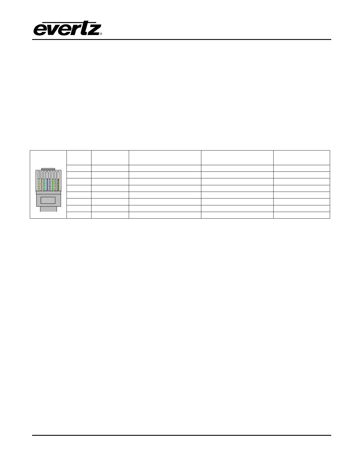
The straight-through RJ-45 cable can be purchased or can be constructed using the pin out information in
Table 2-4. A colour code wiring table is provided in Table 2-4 for the current RJ 45 standards (AT&T 258A
or EIA/TIA 258B colour coding shown). Also refer to the notes following the table for additional wiring
guide information.
Pin # Signal EIA/TIA 568A AT&T 258A or
EIA/TIA 568B
10BaseT
or 100BaseT
1 Transmit + White/Green White/Orange X
2 Transmit – Green/White or White Orange/White or Orange X
3 Receive + White/Orange White/Green X
4 N/A Blue/White or Blue Blue/White or Blue Not used (required)
5 N/A White/Blue White/Blue Not used (required)
6 Receive – Orange/White or Orange Green/White or Green X
7 N/A White/Brown White/Brown Not used (required)
Pin
1
8 N/A Brown/White or Brown Brown/White or Brown Not used (required)
Table 2-4. Standard RJ45 Wiring Color Codes
Note the following cabling information for this wiring guide:
• Only two pairs of wires are used in the 8-pin RJ 45 connector to carry Ethernet signals.
• Even though pins 4, 5, 7 and 8 are not used, it is mandatory that they be present in the cable.
• 10BaseT and 100BaseT use the same pins, a crossover cable made for one will also work with the
other.
• Pairs may be solid colours and not have a stripe.
• Category 5 cable must use Category 5 rated connectors.
The maximum cable run between the HDSD9545DLY-PRO and the supporting hub is 300 ft (90 m). The
maximum combined cable run between any two end points (i.e. HDSD9545DLY-PRO and PC/laptop via
network hub) is 675 feet (205 m).
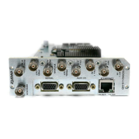
Devices on the Ethernet network continually monitor the receive data path for activity as a means of
checking that the link is working correctly. When the network is idle, the devices also send a link test
signal to one another to verify link integrity. The rear panel is fitted with two LEDs to monitor the Ethernet
connection.
10/100 This Amber LED is ON when a 100Base-TX link is last detected. The LED is OFF
when a 10Base-T link is last detected (the LINK LED is ON). Upon power-up the
LED is OFF as the last detected rate is not known and therefore defaults to the
10Base-T state until rate detection is completed.