HDSD9545DLY - PRO Profanity Bypass Delay Manual
Page 2-2 Revision 1.3.7 INSTALLATION
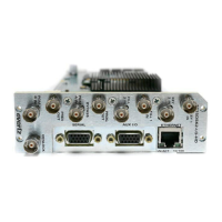
2.1.2. Reference Video Connections
VIDEO REF This BNC input is used for connecting an analog Genlock reference. The genlock signal
may be tri-level sync, NTSC, and is selected by using the Video Reference menu item in
the VIDEO CONFIG menu. Jumper J20 inside the unit selects whether the reference input
is terminated to 75 ohms (default) or high impedance. (See section 4.2.2.1)
REF LOOP/DARS The reference BNCs are shipped as separate 75 ohm terminated inputs for a Video
Reference and Digital Audio Reference Signal. The input BNCs can also be configured as
a high impedance loop for a video reference by removing the top cover of the unit and
changing three jumpers. At the time of writing, use of the DARS reference input is not
implemented.
2.1.3. AES AUDIO Connections
There are four identical sets of AES inputs and outputs for the 4 pairs of AES audio associated with the
video connected to the INPUT A and INPUT B BNCs.
AES 1, AES 2, AES 3, AES 4 INPUT A These 4 input BNC connectors typically provide inputs for the
4 AES pairs of program audio associated with the video connected to the INPUT A video input.
These inputs are protected by bypass relays to the AES OUTPUT A BNCs. The bypass relays
will activate in the event of power loss to the unit and can also be activated from the front panel
or a GPI.
AES 1, AES 2, AES 3, AES 4 INPUT B These 4 input BNC connectors typically provide inputs for the
4 AES pairs of safe audio associated with the video connected to the INPUT B video input.
AES 1, AES 2, AES 3, AES 4 OUTPUT A These 4 BNC connectors provide outputs for the 4 AES pairs
of ‘on-air’ program audio and are normally connected to the main broadcast chain of your plant.
They may also be configured using the AES Out A menu item on the OUTPUT CONFIG menu.
These outputs are protected by bypass relays to the four AES INPUT A input BNCs. When the
bypass relay is activated on power loss, from the front panel, or from a GPI, the four AES
OUTPUT A outputs will be a direct relay connection to the four AES INPUT A inputs.
AES 1, AES 2, AES 3, AES 4 OUTPUT B, C These two groups of 4 BNC connectors provide alternate
outputs for 4 AES pairs of audio and are configured using the AES Out B and AES Out C menu
items on the OUTPUT CONFIG menu. When the bypass relay is activated on power loss the
AES OUTPUT B and C BNCs will not normally have any signal present.
2.1.4. Ethernet Network Connections
ETHERNET This RJ-45 connector is an Ethernet port used for high speed FTP firmware upgrades. See
section 2.6 for information on connecting to an Ethernet network. See section 4.3.1 for
information on upgrading firmware using FTP.