HDSD9545DLY - PRO Profanity Bypass Delay Manual
INSTALLATION Revision 1.3.7 Page 2-3
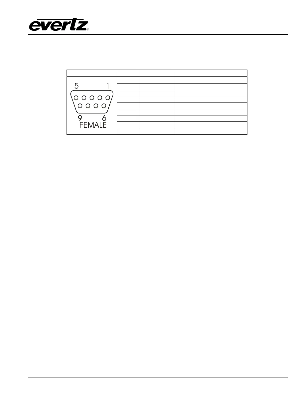
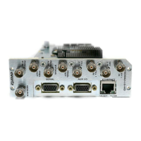
2.1.5. Serial I/O and GPI/O Connections
REMOTE CTL This 9 pin female D connector provides an RS-232 serial interface used for updating the
firmware. This port is wired at the factory as an RS232 DCE port as shown in Table 2-1.
Pin # Name Description
1 GND Chassis ground
2 TxD RS-232 Transmit Output
3 RxD RS-232 Receive Input
4
5 Sig Gnd RS-232 Signal Ground
6
7 RTS RS-232 RTS Input
8 CTS RS-232 CTS Output
9
Table 2-1: Remote CTL Port Pin Definitions
GPI/O This female DB-25 pin connector provides 8 General Purpose Opto-isolated inputs (GPIs) and
4 General Purpose isolated relay outputs (GPOs). Vint provides +5Volts from the unit and
Vext is used to provide external power to the opto-isolators. Typically Vint and Vext are
connected together so that the isolators may be powered from the unit. Table 2-2 shows the
pin definitions of the GPIO connector. Figure 2-2 shows a schematic of the GPIO circuitry.
See section 2.7 for more information on connecting the General Purpose inputs and outputs.
The GPIs are used as additional triggers to initiate a transition such as a video and/or audio
switch. The GPOs are used to trigger external devices and a transition tally capability. The
GPI and GPO functions can be programmed using the TRANSITION menu. See section 3.8.