HDSD9545DLY - PRO Profanity Bypass Delay Manual
Page 2-4 Revision 1.3.7 INSTALLATION
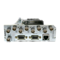
Pin
#
Name Description
1 GPI 01 General Purpose Input 01
2 GPI 02 General Purpose Input 02
3 GPI 03 General Purpose Input 03
4 GPI 04 General Purpose Input 04
5 GPI 05 General Purpose Input 05
6 GPI 06 General Purpose Input 06
7 Tx+ RS-422 Tx+(b) Output
8 Tx- RS-422 Tx-(a) Output
9 GND Serial I/O Ground
10 Rx+ RS-422 Rx+(b) Input
11 Rx- RS-422 Rx-(a) Input
12 SELECT RS-422/232 Select (Gnd for RS232)
13 GPI 07 General Purpose Input 07
14 GPI 08 General Purpose Input 08
15 Vext External voltage input to power opto isolators
16 Vint Protected +5 volts output from unit
17 GPO 01 NC General Purpose Output 01 Normally closed contact
18 GPO 01 C General Purpose Output 01 Common contact
19 GPO 02 NC General Purpose Output 02 Normally closed contact
20 GPO 02 C General Purpose Output 02 Common contact
21 GPO 03 NC General Purpose Output 03 Normally closed contact
22 GPO 03 C General Purpose Output 03 Common contact
23 GPO 04 NC General Purpose Output 04 Normally closed contact
24 GPO 04 C General Purpose Output 04 Common contact
25 GND Unit Chassis ground
Table 2-2: GPI/O Port Pin Definitions
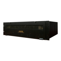
2.1.6. Power Connections
The main unit has one or two universal voltage power supplies that operate on 100 to 240 Volts 50/60 Hz
AC.
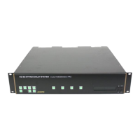
2.2. MOUNTING
The HDSD9545DLY-PRO is equipped with rack mounting angles and fits into a standard 19 inches by 3.5
inches (483 mm x 89 mm) rack space. The mounting angles may be removed if rack mounting is not
desired.
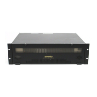
2.3. POWER REQUIREMENTS
Power requirements are 100 to 240 volts AC at 50 or 60 Hz. The HDSD9545DLY-PRO has universal
power supplies that automatically sense the input voltage. Power should be applied by connecting a 3-
wire grounding type power supply cord to the power entry module on the rear panel. The power cord
should be minimum 18 AWG wire size; type SVT marked VW-1, maximum 2.5 m in length. If the units are
fitted with the redundant power supply there will be an additional IEC-320 connector on the rear panel.
The power entry module combines a standard power inlet connector, two 5 x 20 mm fuse holders and an
EMI line filter.