TR-4800E
Tally Router
Revision 1.1 Page - 5
3 INSTALLATION
The Tally router is designed to fit into standard 19” equipment racks. Installation in a 19” rack is simple.
Guide the unit through the aperture in the front of the rack until the rack-mounting flanges are flush
against the side member of the rack and bolt in place with fixing screws (not supplied). Behind the unit
a clearance of 8” (200mm) should be provided for the connection of external cables.
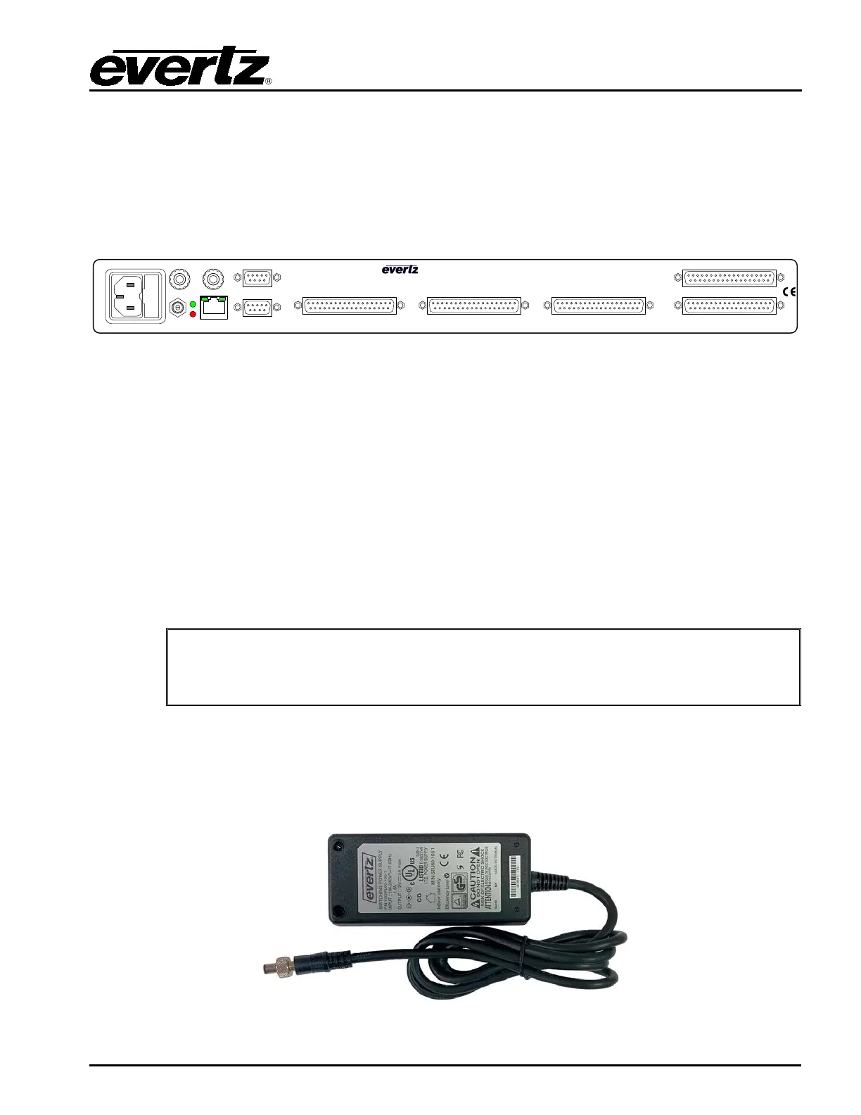
Figure 2-1: Rear Panel of TR-4800E
3.1 POWER CONNECTIONS
The TR-4800E power supply has an IEC320 C14 AC power inlet. This combines a standard power inlet
with a fuse holder and EMI line filter. The inlet is fused from the factory for 120V with two fuses rated
for 2 amps (T2AL250V). If the tally router is being used with 200V AC or higher, these fuses should be
reduced to 1 amps (T1AL250V). The fuse holder can be removed once the power cord is unplugged by
levering it out with a small screwdriver.
There in no power switch. The unit will power on as soon as the AC power is connected. The power
supply is auto-ranging and can operate on 90-132 or 180-264 volts AC at 50Hz or 60Hz. Power should
be applied by connecting a 3-wire grounding type power supply cord to the power entry modules on the
rear panel. The power cord should be minimum 18 AWG wire size; type SVT marked VW-1, maximum
2.5 m in length.
The AC inlet EMI line filter uses the chassis ground as part of the circuit. This
generates a small amount of AC leakage current to ground. In order to reduce risk
of electric shock, the u
nit MUST be grounded properly through the ground
connections on the AC power supply inlets.
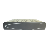
A 12V DC barrel (2.5x5mm) connection on the rear of the frame can be used with the provided 12V DC
external power supply. This provides the tally router with a redundant power supply and allows it to
continue operating if a power fault occurs in one of the supplies. Ideally, the tally router AC inlet and
the external 12V DC power supply should be powered by separate AC sources to provide true
redundancy. When the 12V DC connection in plugged in, thread the locking collar tightly to prevent
accidental removal.
Figure 2-2: External AC Adapter Power Supply (12V DC)