TR-4800E
Tally Router
Page - 10 Revision 1.1
3.5 OUTPUT PORTS
There are 48 General Purpose Outputs (GPOs) available on three 37-pin D-Sub connectors on the
rear on the tally router. These connectors are labelled “Output1 (1-16)”, “Output 2 (17-32)” and
“Output3 (33-48)”. The GPOs are “Dry” meaning no Wet voltage is present. The GPOs can be used to
activate tally lights or send triggers to equipment such as the Evertz VIP multiviewers, switchers, and
keyers. They can also be used to drive camera tally lamps. The pinout of these connectors are not all
the same and care must be taken to use the correct wiring (see Table 2-8, Table 2-9, and Table 2-10).
Please Note: The Outputs 1 connector uses a different pinout than Outputs 2/3.
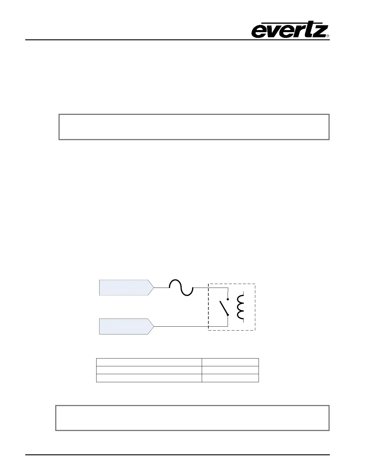
The General Purpose Outputs are not polarity sensitive. Each GPO has two pins marked “A” and “B”.
The GPO consists of an isolated relay contact pair. When the GPO is closed, the two contact “A” and
“B” will be electrically connected to each other. See Figure 2-4 for the circuit diagram of a GPO.
Each GPO is protected against excessive current with a polyfuse. Polyfuses operate by means of
thermal limiting. The maximum allowable current is shown in Table 2-7. If excessive current is applied
to the GPO the polyfuse will heat up and open. This process happens very quickly if the current is high
but may take hours if the current is only a little above the maximum. When the polyfuse opens, it
immediately begins to cool and will eventually reset on its own. If the fault is not removed, the process
will repeat itself any may cause a “strobing” effect on any load devices connected to the GPO.
The currently selected Wet Power source is available on five pins of the D-Sub connector. The WET-
pin is isolated from chassis ground when using an external wet power source. It is connected to
chassis ground when using the internal +5V or +12V wet power sources. The WET+ voltage can be
used to wire the GPOs as “Wet”. Please see section 2.7 for more information.
Figure 2-4: Rear General Purpose Output Circuit Diagram (Dry)
Closed Contact Resistance
Table 2-7: Rear General Purpose Output Electrical Specifications
Do not exceed the maximum voltage specified or the GPO may be damaged.