TR-4800E
Tally Router
Page - 8 Revision 1.1
3.4 GENERAL PURPOSE INPUTS
There are 32 General Purpose Inputs (GPIs) available on two 37-pin D-Sub connectors on the rear on
the tally router. These connectors are labelled “Inputs1 (1-16)” and “Inputs2 (17-32)”. The GPIs are
“Wet” meaning they need external voltage to function. The GPI ports are used to read the tallies
(GPOs) from products such as a vision mixer (production switcher). The pinout of these connectors is
similar and is shown in Table 2-6 and Table 2-7.
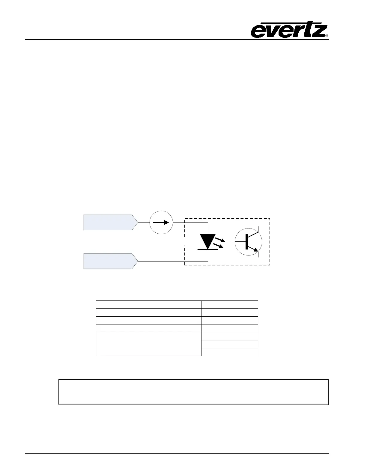
Note that the GPI is polarity sensitive. The circuit diagram is shown in Figure 2-3 and the electrical
specifications are in Table 2-4. The GPI input voltage drives a current source into an optoisolator. The
optoisolator is used to protect the tally router’s internal circuitry, and also to isolate the GPIs from each
other. If more than +/- 24 volts is applied to a GPI it may become damaged but the damage will be
isolated to the particular GPI.
The currently selected Wet Power source is available on five pins of the D-Sub connector. The Wet
Power negative (–) pin is isolated from chassis ground when using an external wet power source. It is
connected to chassis ground when using the internal +5V or +12V wet power sources. This Wet power
can be used to wire the GPIs as “Dry”. Please see section XXXXX for more information on the wiring
and the Wet/Dry terminology.
GPI +
GPI -
~10 mA
~1.4 V
optoisolator
Figure 2-3: Rear GPI Input Schematic
Maximum Reverse GPI Voltage
GPI Current
Table 2-4: Rear GPI Input Electrical Specifications
Do not apply a voltage higher or lower than the maximums or the GPI may be
permanently damaged.