TR-4800E
Tally Router
Page - 6 Revision 1.1
3.2 ETHERNET CONNECTION
The TR-4800E is equipped with a Gigabit Ethernet port. It can be used with either 100base-TX (100
Mbps) or 1000base-T (1 Gbps) twisted pair Ethernet networks. Category 5e UTP cable or better is
required with a maximum length of less than 100 meters (328 feet). The cable must be “straight
through” with an 8-pin modular connector at each end. Make the network connection by plugging one
end of the cable into the tally router and the other end into an Ethernet hub or switch.
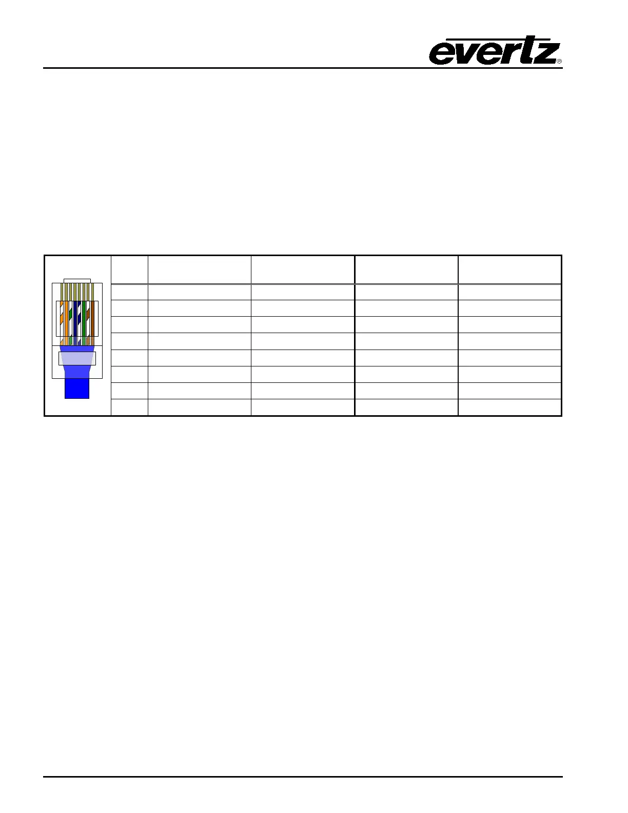
The straight-through Ethernet cable can be purchased or can be constructed using the pinout
information in Table 3 1. A color code wiring chart is provided in Table 3 1 for the current Ethernet
standards (AT&T 258A or EIA/TIA 258B color coding shown). Also refer to the notes following the table
for additional wiring guide information.
Pin# EIA/TIA 568A
AT&T 258A or
EIA/TIA 568B
100Base-TX 1000Base-T
2 Green Orange Transmit –
3 White/Orange stripe White/Green stripe Receive +
4 Blue Blue Not Used (required)
5 White/Blue stripe White/Blue stripe Not Used (required)
6 Orange Green Receive –
Table 2-1: Standard 8-pin Modular Connector Wiring Color Codes
The gigabit Ethernet port has two green LEDs marked “LNK” and “ACT”. The “LNK” LED will illuminate
green when the connection speed is 1000base-T and will be off for 100base-T. The “ACT” LED will
blink green with Ethernet activity. The Ethernet standard mandates auto-negotiation so crossover
cables are no longer required. The initial TCP/IP settings of the unit can be set through the
configuration serial port (Serial 1).