TR-4800E
Tally Router
Revision 1.1 Page - 17
Closed Contact Resistance
Table 2-12: Front GPIO Channel GPO Electrical Specifications
Do not exceed the maximum voltage specified or the GPO may be damaged.
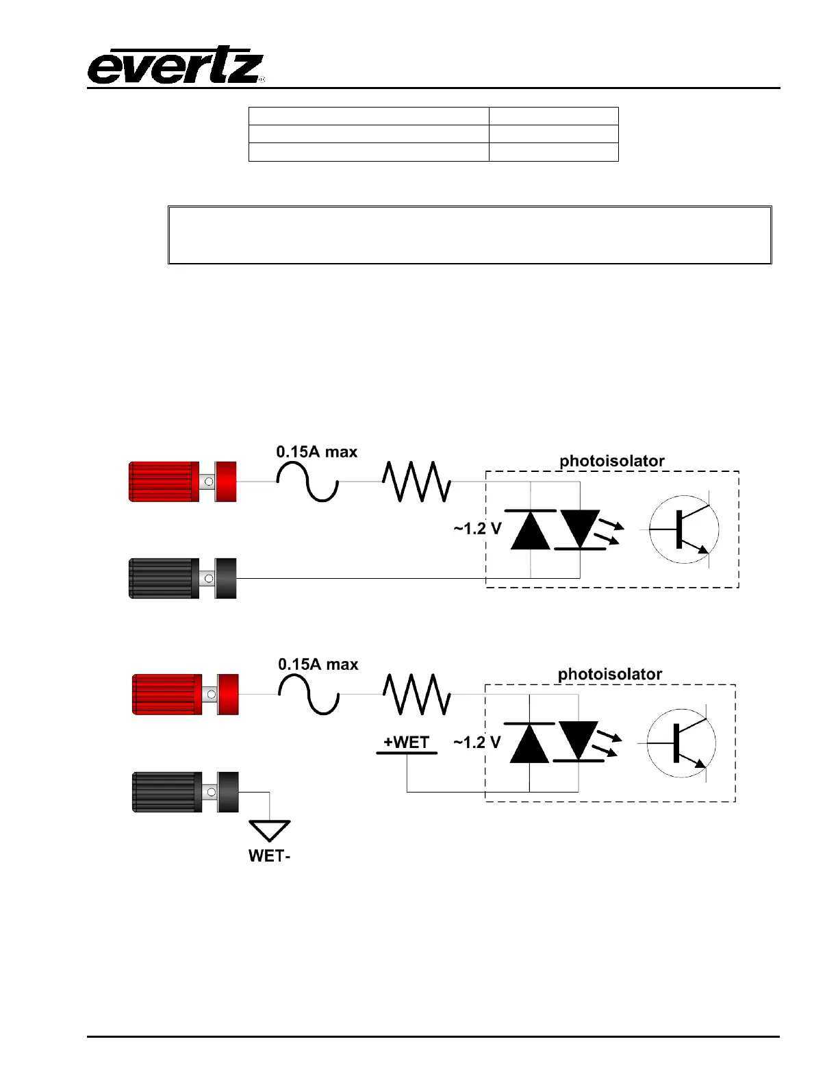
3.8.2 Binding Post Inputs
When a GPIO channel has been configured as a GPI, the respective “OUT” LED will turn off. The GPI
can be switched between Wet and Dry modes (see section 2.7.1). When the GPI is in Wet mode the
“WET” LED will illuminate. In Wet mode the GPI can be turned on by applying voltage in either
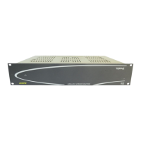
direction. It is not polarity sensitive like the rear GPIs. When the GPI is in Dry mode the red binding
post will have +WET voltage on it. It can be activated by connecting the red binding post to the black.
The “ON” LED will illuminate any time the GPI is activated.
Figure 2-8: Front panel GPIO in Wet GPI Mode Circuit Diagram
Figure 2-9: Front GPIO Channel in Dry GPI Mode Circuit Diagram