TR-4800E
Tally Router
Revision 1.1 Page - 19
3.9.1 TR4800-BHP General Purpose Output Connections
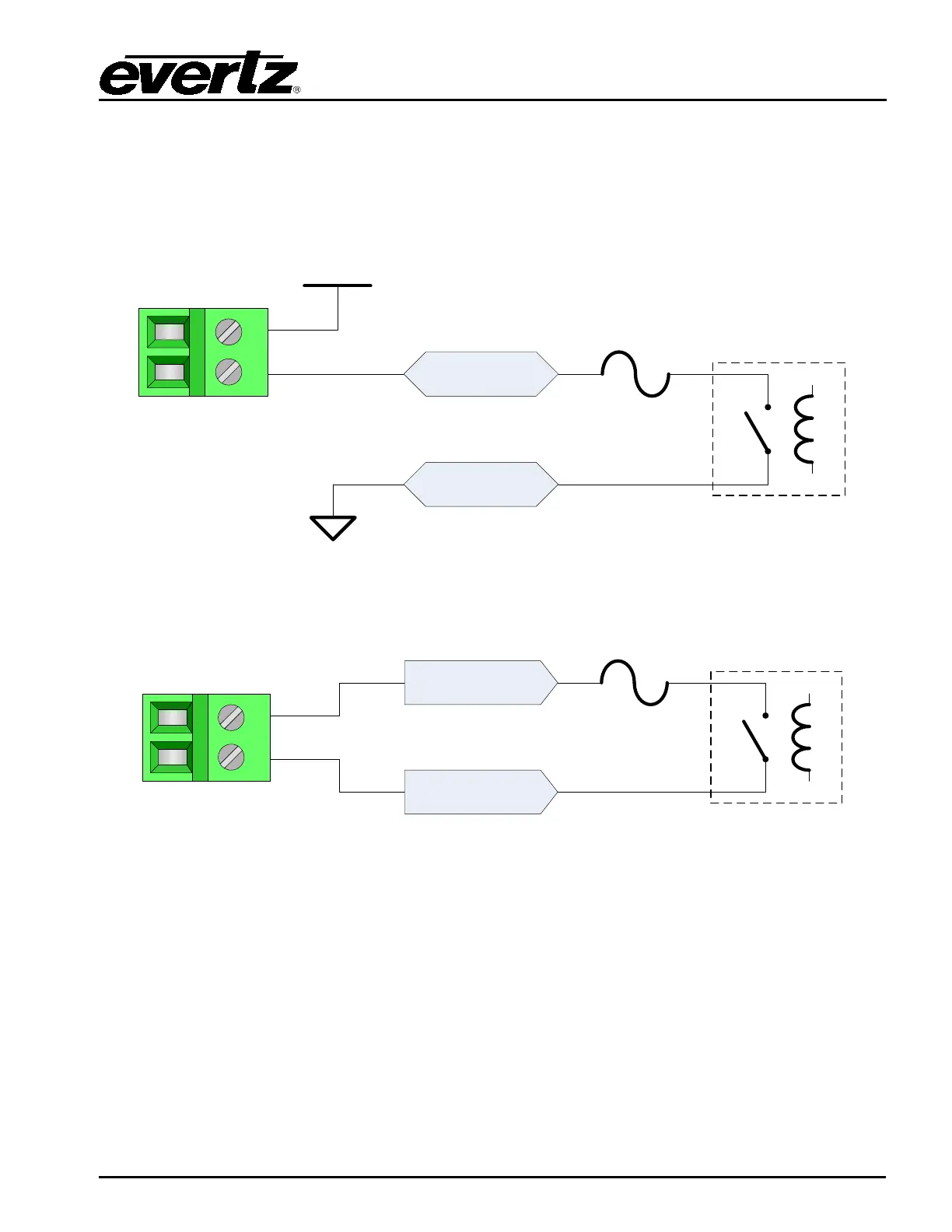
The rear 48 General Purpose Outputs from the tally router are broken out to 48 terminal blocks across
the top of the bulkhead panel. Each GPO has a slide switch below it to select between Wet and Dry
modes (see section 2.7.1). The circuit diagrams for the GPOs in both modes are shown in Figure 2-11
and Figure 2-12.
GPO B
0.15A max
WET GPO
1
2
+WET
GPO A
WET-
Figure 2-11: TR4800-BHP GPO in Wet Mode Circuit Diagram
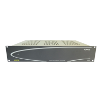
GPO A
GPO B
0.15A max
DRY GPO
1
2
Relay
Figure 2-12: TR4800-BHP GPO in Dry Mode Circuit Diagram