58
04011210
EXCELL PRECISION CO., LTD
ZSME400000003
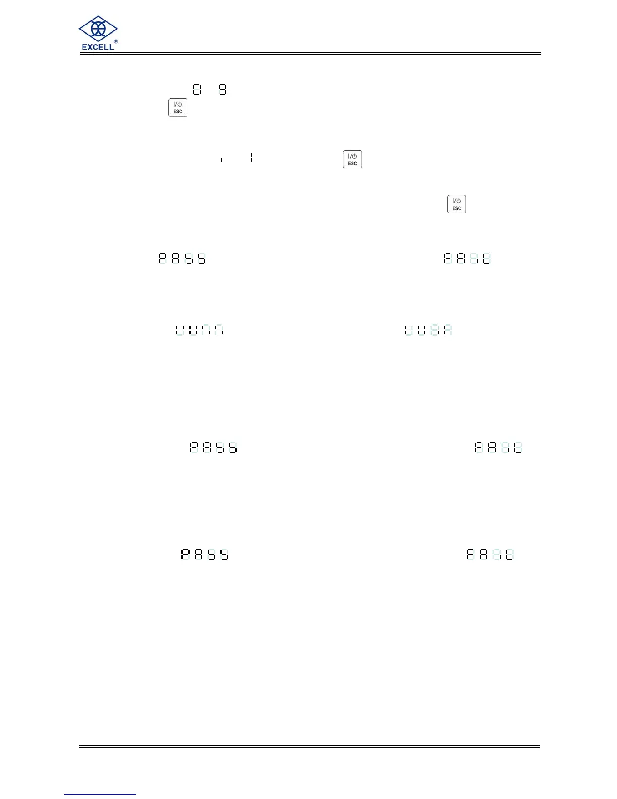
6-3-1 7-Segment display testing
The display will show ~ , then display “.” and all of the icons.
To exit press the key
6-3-2 Keypad and calibration SW testing
Setting the calibration SW to “ON”, or pressing any key will cause the related display
segment to change from → . To exit press the key
6-3-3 Display A/D internal value display
Display range is 0 ~ 520,000d (-0.1mV/V ~ 4.0mV/V). To exit press the key
6-3-4 RS-232 serial loop back testing
Terminal pin 7 and pin 8 must be connected together at the rear of the indicator.
If display shows , the interface is working normally. If display shows ,
the interface is not working correctly.
6-3-5 EEPROM memory testing
If the display shows , it means normal. If the display shows , the memory is
not working correctly.
6-3-6 Option interface card testing
OP-01 RS232/RS422/RS485 testing
1) RS232 testing
J1~J4
⇒ 1, 2 short (Adjust J1~J4 mini jumper to 2, 3)
Terminal pin 1 and pin 3 must be connected together at the rear of the indicator.
If display shows , the interface is working normally. If display shows ,
the interface is not working correctly.
2) RS422 testing
J1~J4
⇒ 1, 2 short (Adjust J1~J4 mini jumper to 1, 2)
J5~J6 ⇒ 1, 2 short (Adjust J5~J6 mini jumper to 1, 2)
Terminal pin1 and pin 3, pin 2 and pin 4 must be separately connected together at the
rear of the indicator.
If display shows , the interface is working normally. If display shows
the interface is not working correctly.
OP-02 BCD parallel output interface testing
1) A flashing decimal point indicates the test procedure is active.
2) Program will transmit OFF → ON → OFF signal for each output bit of the BCD interface in
sequence.