Do you have a question about the Excell EX-2001 Racer Plus and is the answer not in the manual?
Guides users to set general functions by referencing the Function Table.
Guides setting of capacity parameters like decimal point, max capacity, and min division.
Details the procedures for calibrating the instrument.
Explains how to access and use the self-diagnosis mode for troubleshooting.
Instructs on resetting all parameters to factory default settings.
Guides resetting general function parameters to factory standards.
Procedure to view the instrument's software version.
Details setting of Hi, Lo, and Zero Band parameters.
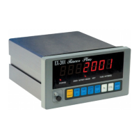
Details the components and indicators on the front panel of the instrument.
Illustrates the rear panel layout and connection points.
Provides wiring instructions for connecting load cells.
Details the process of installing the indicator into a control panel.
Details how to set various parameters before calibration.
Explains the step-by-step process for instrument calibration.
Details the procedure for setting and managing the instrument's password.
Provides a reference for understanding and troubleshooting error messages.
Details the activation and operation of the animal scale function.
Explains the RS-422 and RS-485 serial interface options.
Details the Parallel BCD Output interface and its pin assignments.
Covers the Analog Current/Voltage Output interface specifications.
Describes parallel printer, RS-232, and current loop interface options.
Details the RS-232 and Current Loop interfaces.
Explains RS-232, Current Loop, and Data Clock output features.
Describes the Control I/O interface with external input and relay output.
Guides users on resetting all instrument parameters to their default state.
Explains how to reset only general function parameters to factory standards.
Checks the functionality of the 7-digit display and status indicator lights.
Verifies the operation of the keyboard and calibration switch.
Diagnoses the RS-232 serial output and input interface.
Checks the functionality of the BCD parallel output interface.
Diagnoses the Analog Current Output interface.
Checks the operation of the Parallel Printer interface.
Verifies the integrity of the EEPROM memory on the main board.
Diagnoses the Control I/O (2I/4O) interface.
Provides a table of general functions and their settings.
Lists functions related to serial and current loop interfaces.
Specifies functions for the Parallel BCD Output interface.
Lists functions for the Analog Output interface, including data type and values.
Specifies functions for the Parallel Printer Output interface.
Lists functions for the Control I/O interface.
| Model | EX-2001 Racer Plus |
|---|---|
| Category | Accessories |
| Interface | USB |
| Pedals | Yes |
| Force Feedback | Yes |
| Type | Steering Wheel |
| Compatibility | PC, PlayStation |