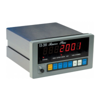
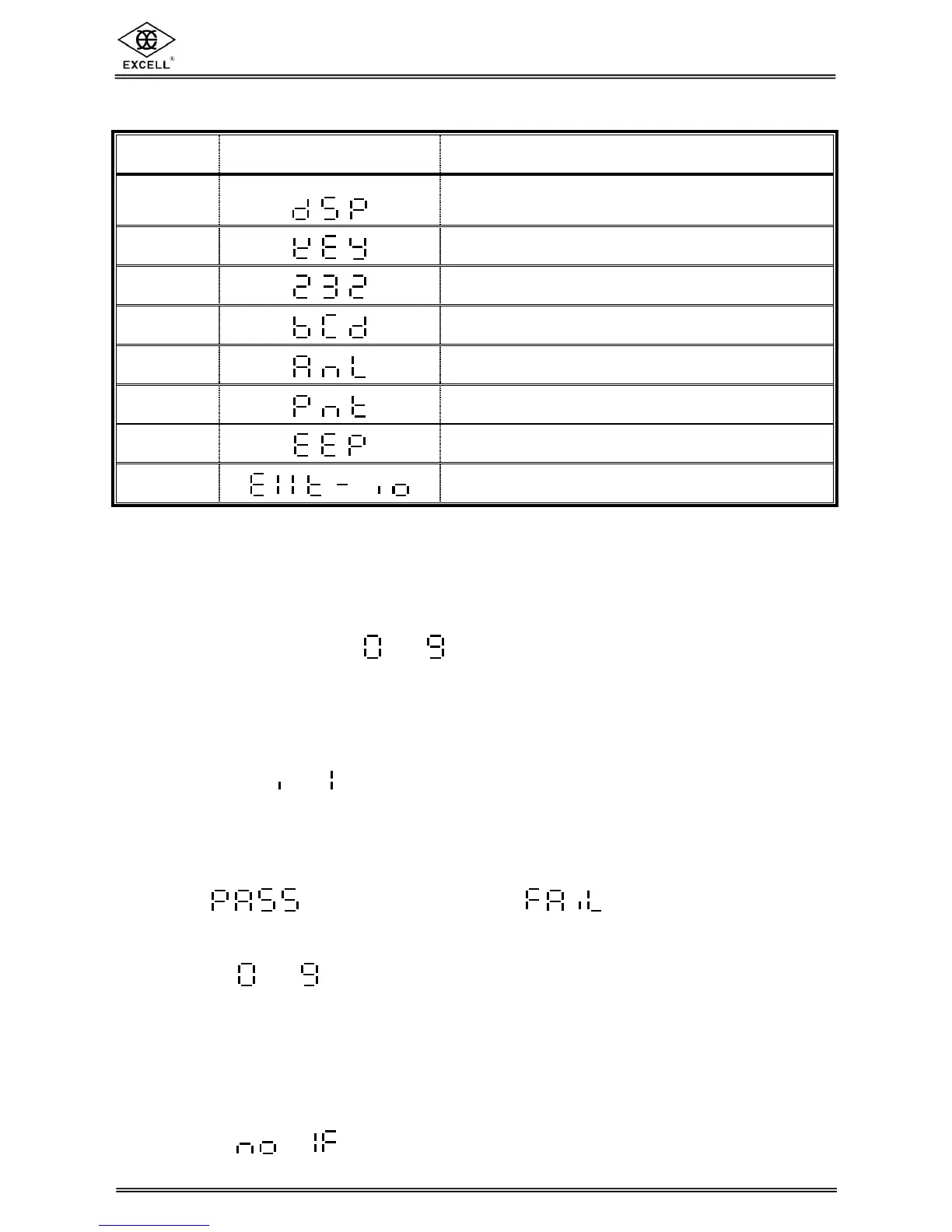
No. Display Diagnosis Item
1
7 digits display and LED status lights
2
Keyboard and calibration ON / OFF switch
3
OP-06 RS-232 serial output / input interface
4
OP-02 BCD parallel output interface
5
OP-03 Analogue current output interface
6
OP-05 Parallel printer interface
7
EEPROM memory on main board
8
OP-08 Control I/O interface
8-3-1 7 Digit Display and LED Status Light Diagnosis
7 digit display shows ~ , “.” And at the same time, the LED status
lights turn on and off in order.
8-3-2 Keyboard and Calibration ON / OFF Switch Diagnosis
Switch the calibration switch to “ON”, or press any keys and the corresponding digit
goes from → on the display.
8-3-3 RS-232 Serial Output / Input Interface Diagnosis ( OP-06 )
(1) Short circuit the 2
nd
pin and 3
rd
pin of the SER. OUT. D-SUB 25 pin connector.
= Working properly = Malfunction
(2) If connecting to a computer (The communication protocol has to be compatible),
if ~ can be read, it indicates that the RS-232 is in working order.
8-3-4 BCD Parallel Output Interface Diagnosis ( OP-02 )
(1) The decimal point flashes during the diagnosis.
(2) The program sends out OFF→ON→OFF signals from each of BCD output bit.
(3) If is displayed, this indicates that no BCD interface is installed.