Maintenance
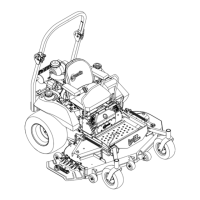
g239055
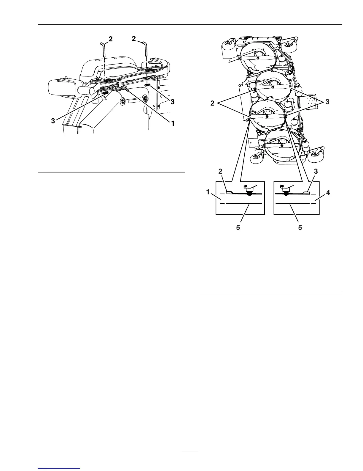
Figure47
1.Unlockcamlock3.Lanyard
2.Clevispin
8.Inserttheheightadjustmentpinintothe4inch
(102mm)cuttingheightlocationandreinstallthe
lanyard.
9.Locktheleftandrightwingdeckcamlocks.
10.Startengine.Brakemustbeengagedand
motioncontrolleversouttostartengine.
Operatordoesnothavetobeintheseat.Be
surethatallpersonsareclearofthedeckwings.
Pressandholdthefrontofthedeckcontrol
switchuntilthecenterdecklowersandbothwings
arecompletelyunfoldedtothecuttingheight.
11.Stopengine,waitforallmovingpartstostop,
engagetheparkingbrakeandremovethekey.
12.Measurefromthelevelsurfacetothefronttip
oftheLHandRHcenterdeckblades.The
measurementshouldread4inches(102mm).
g239092
Figure48
1.41/4inches(108mm)
2.Backbladetip
3.Frontbladetip
4.4inches(102mm)
5.Levelsurface
AdjustingtheCenterDeck
1.Adjusttheheight—toincrease,turnthe
adjusterscrewclockwise;todecrease,turn
counterclockwise.
Loosenthejamnutsonthetopofeachdeck
adjuster.Finetunetheadjusteronthefrontdeck
liftassemblybyturningittogetthecorrectheight
forthecenterdeckleftandrightfrontbladetips
(seeFigure49).
2.Measurethebacktipheight.Finetunerear
adjustersasrequired;thesinglepointadjustment
canbeutilizedtogainmoreadjustment.
3.Re-measureuntilallfoursidesarethecorrect
height.Tightenallthenutsonthedeckliftarm
assemblies.
59

 Loading...