Video
X is clock input
Y is modify input
Z sets the randomness
A is quantized CV output
B is trigger output
Outputs & Receives MIDI
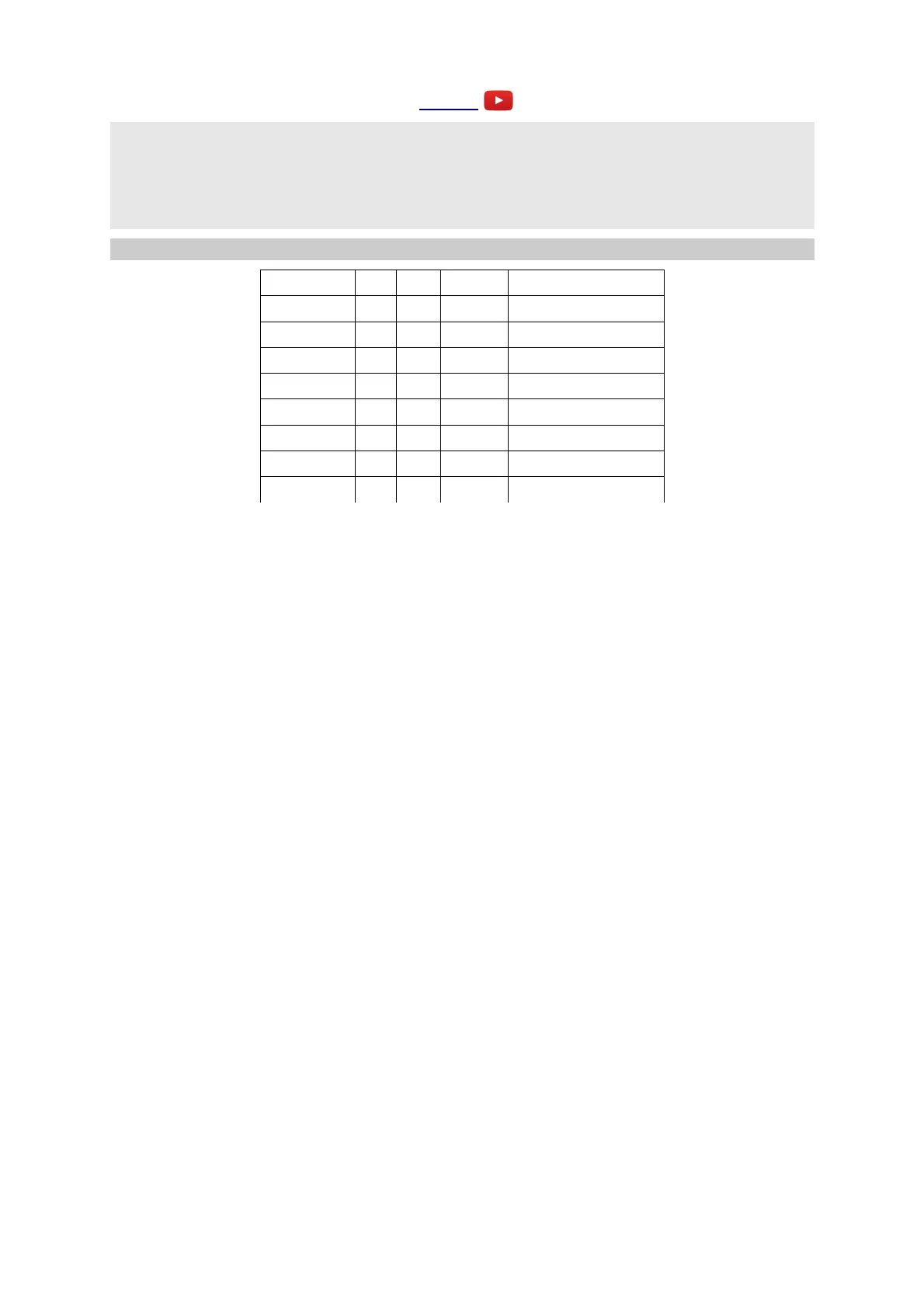
Parameter Min Max Default Description
0 0 1 0 Direction.
1 1 32 8 Length.
2 0 15 0 Scale.
3 -40 40 32 Output attenuverter.
4 0 1 0 MIDI Gate.
5 -48 48 0 Transpose.
6 0 31 0 Slew.
7 0 15 0 MIDI clock divisor.
This algorithm generates random CVs via the popular rotating shift register method. The joy of this
method is that it generates a loop of CVs, with a controllable likelihood of change, including the
possibility to lock the loop so it does not change. The CVs are quantized to semitones or to a chosen
musical scale.
X is the clock input. Any clock pulse in excess of 1V can be used. On each rising edge the shift
register rotates and a new CV is output. On each rotation, there is the possibility that one bit of the
shift register will be flipped, changing the pattern. The likelihood of a flip is set by Z. When Z is
zero there is a 50% chance that the bit will flip, which is the most random setting. As Z rises, the
chance of a flip reduces, until at around 2V the chance of a flip hits zero and the pattern is
effectively locked. Conversely, as Z goes negative, the chance of a flip goes up, reaching 100% at
around -2V. This also effectively locks the pattern, but at twice the length (since it is alternating
between the locked pattern and its inverse). When Z crosses the ±2V boundaries, in either direction,
the display shows "**" for a short while to let you know that the pattern has been locked or
unlocked.
Input Y allows for modification of the sequence, even when the loop is locked. If input Y is above
1V, the bit will always be flipped on a clock pulse, regardless of the setting of Z.
Output A is the random pattern of CVs, quantized to the scale chosen via parameter 2. The list of
scales is the same as that for the Quantizer algorithm, above.
Output B is a trigger output.
Parameter 0 sets the direction of rotation. The two directions have a different sound to the patterns
they tend to generate.
Parameter 1 sets the length of the shift register, and so the length of the repeating CV pattern in
terms of clocks.
Parameter 3 is an attenuverter for the random CV, applied before quantization.
Parameter 5 is a transpose amount, in semitones, applied after quantization.
Parameter 6 sets the output slew rate. This has the same effect as the Slew Rate Limiter algorithm
being applied to output A.
Page 56
 Loading...