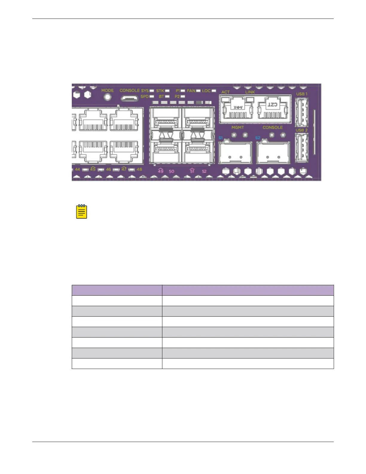
The following figure shows the two alternate mode LEDs for 5420 Series switches: SPD and STK. The
Mode button is used to cycle through three display modes for the port LEDs. In the default mode, SPD
and STK are o. SPD and STK display modes expire after 30 seconds, at which time the port LEDs
revert to the default SYS mode. Pressing and holding the the Mode button initiates Bluetooth pairing.
Figure 58: 5420 Series Mode and System Status LEDs
Note
Front-panel PoE ports use Amber to indicate PoE states.
Port LEDs in Default (SYS) Mode
In the default SYS mode, SPD is OFF, and the port status displays behavior for link, trac, and PoE as
described in the following table:
Table 24: Port LEDs in SYS Mode (default)
Color/State Meaning
Steady green Link is OK; port is not powered
Steady amber Link is OK; port is powered; no trac
Blinking green Link is OK and transmitting packets; port is not powered
Blinking amber Link is OK and transmitting packets; port is powered
Slow blinking amber No link, or disabled port; port is powered
Alternating amber and green Port has a power fault
O Port is not powered, has no link, or is disabled
Port LEDs in SPD Mode
The port LEDs enter the SPD display mode after the Mode button is pressed once, indicated by the SPD
LED. SPD mode is used to help determine the operational speed of a port.
There are two LEDs per QSFP28 port on 5420 models. In stack mode, the first LED represents the link
state and trac of the stack port with solid or blinking green. When a QSFP28 port is used for Ethernet
Monitoring the Device
Port LEDs in Default (SYS) Mode
ExtremeSwitching 5420 Series Hardware Installation Guide 95
 Loading...

