Figure 44: SummitStack Configuration Using Dierent Switch Models and
SummitStack 40G Cables
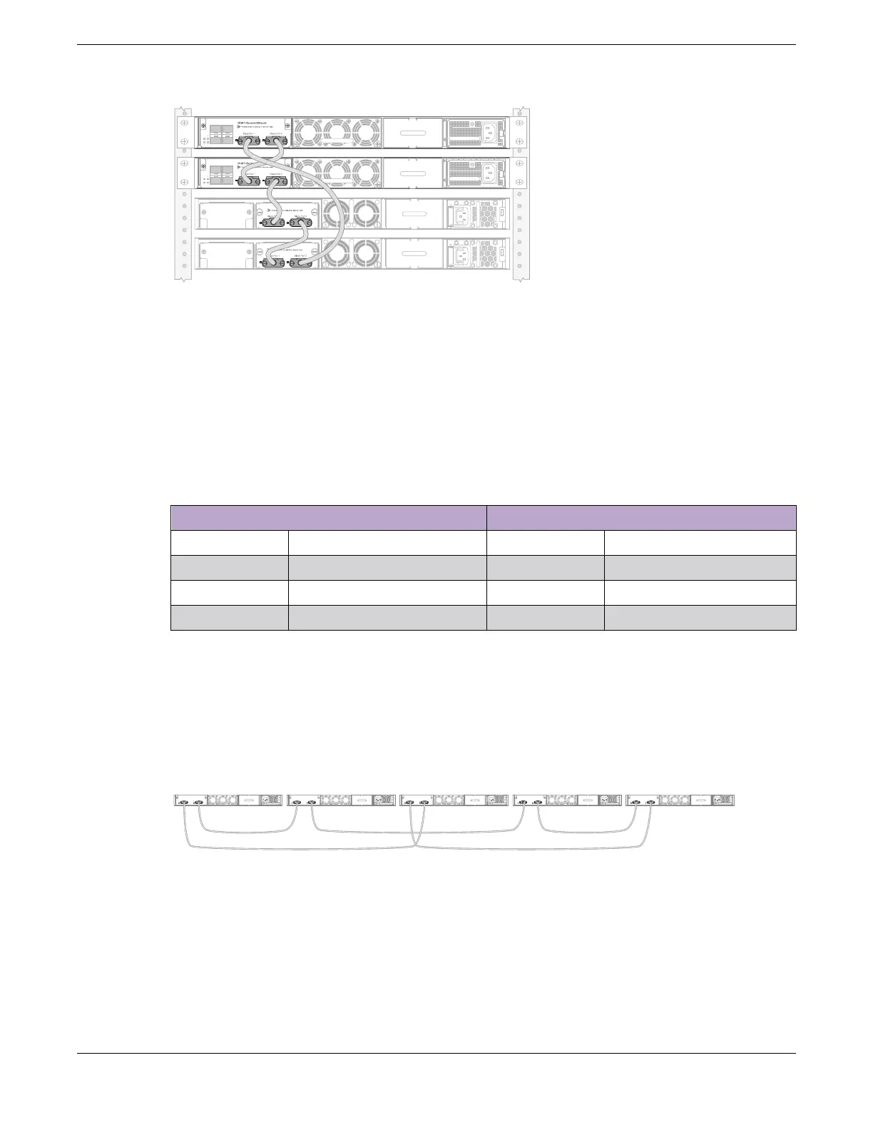
Example: Stacked Switches across Two Racks
The following example shows four switches – two of one model, two of another model – physically
located in two adjacent racks.
Table 24 lists the recommended order for connecting the stacking ports in this example.
Table 24: Stacked Switches across Two Racks: Connections
Connect this slot and port . . . . . . To this slot and port
Slot 1 Stack Port 2 Slot 2 Stack Port 1
Slot 2 Stack Port 2 Slot 3 Stack Port 1
Slot 3 Stack Port 2 Slot 4 Stack Port 1
Slot 4 Stack Port 2 Slot 1 Stack Port 1
Example: Stacked Switches across Several Racks
Figure 45 shows five switches installed at the tops of five adjacent racks. To accommodate the shortest
possible cables, immediately adjacent switches are not always connected together. Port 2 on one switch
is connected to Port 1 on the next connected switch. If the easy setup feature is used to configure the
stack parameters, the assigned slot numbers will be as shown in the figure.
Slot 1 Slot 2 Slot 3 Slot 4Slot 5
Rack A
Rack B Rack C Rack D Rack E
Figure 45: Top-of-Rack Stack Installation
Building Stacks
Connecting the Switches to Form the Stack Ring
ExtremeSwitching 5520 Series Hardware Installation Guide 69
 Loading...

