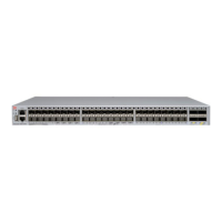
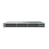
FIGURE 8 Non-port-side view of the DC VDX 6740
1. Power supply and fan assembly #2
2. Power supply and fan status LED
3. On/o switch
4. Power cord receptacle
5. Handle
6. Airow label
7. Captive screw
8. Power supply and fan assembly #1
FIGURE 9 Non-port-side view of the AC VDX 6740
1. Power supply and fan assembly #2
2. Power cord receptacle
3. Power supply and fan status LED
4. On/o switch
5. Handle
6. Airow label
7. Captive screw
8. Power supply and fan assembly #1
The following illustration shows the non-port side of the VDX 6740T, which house the separate power supplies and fans.
NOTE
The un-numbered features on the DC power supply are identical to the features on the AC power supply.
Hardware components
ExtremeSwitching VDX 6740 Hardware Installation Guide
9036108-00 21

 Loading...


