Operation and Maintenance
• LED activity interpretation..............................................................................................................................................................................99
• POST and boot specications..................................................................................................................................................................104
• Interpreting POST results............................................................................................................................................................................104
• Powering o the device................................................................................................................................................................................105
• Thermal operations........................................................................................................................................................................................105
• Device maintenance......................................................................................................................................................................................105
• Device management.....................................................................................................................................................................................108
LED activity interpretation
System activity and status can be determined through the activity of the LEDs on the device.
There are three possible LED states: o (no light), a steady light, and a ashing light. Flashing lights may be slow, fast, or ickering. The
LED colors are either green or amber. Refer to LED patterns on page 101 for details on LED behavior.
Sometimes, the LEDs ash either of the colors during boot, POST, or other diagnostic tests. This is normal; it does not indicate a
problem unless the LEDs do not indicate a healthy state after all boot processes and diagnostic tests are complete.
LEDs
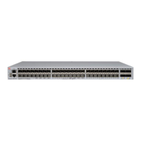
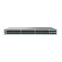
The ExtremeSwitching VDX 6740 devices have the following LEDs:
• One bicolor system status LED (green and amber) on the port side.
• One power status LED (green) on the port side.
• Two Ethernet management port LEDs (green) for the Ethernet management port. The two LEDs show the status of the port link
and the port activity.
• One triangle-shaped bicolor port status LED (green and amber) for each 10 GbE port. These LEDs are arrayed above each
vertical port.
• One triangle-shaped bicolor port status LED (green and amber) for each 40 GbE port. These LEDs are arrayed between each
vertical pair of 40 GbE ports. The left LED corresponds to the upper port of the pair and the right LED corresponds to the lower
port.
• One power supply and fan assembly LED (green) above the AC or DC power switch on each combined power supply and fan
assembly on the non-port side of the VDX 6740.
• One power supply LED (green) to the left of the AC or DC power plug on each power supply on the non-port side of the VDX
6740T.
• One bicolor fan status LED (green and amber) on each fan assembly on the non-port side of the VDX 6740T.
LED locations
On the VDX 6740, the port status LEDs for the external ports are situated between the upper and lower ports of each pair. On the VDX
6740T, the port status LEDs for the 10 GbE ports are situated above the upper and lower ports of each pair. The port status LEDs for
the 40 GbE ports are situated between the upper and lower ports of each pair as on the VDX 6740. Refer to the following illustration.
ExtremeSwitching VDX 6740 Hardware Installation Guide
9036108-00 99

 Loading...


