1 = Grouding lug 3 = SSD slot 5 = Power supplies
2 = RJ45 console and management ports 4 = Fan modules
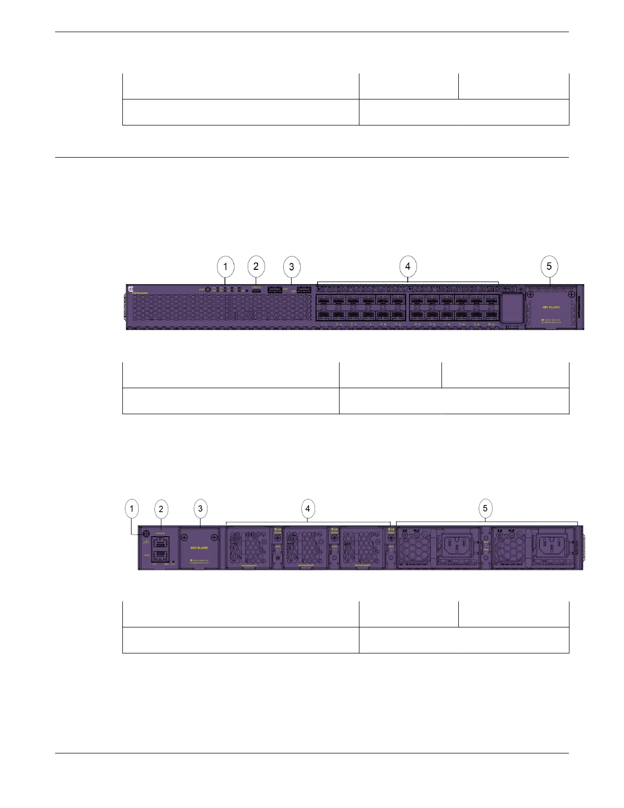
VSP4900-24S Switch Features
The front panel of the ExtremeSwitching VSP4900-24S switch includes:
• 24 100/1000Mb SFP ports
• 1 VIM5 slot
• 2 USB A ports
• 1 USB micro B management port
Figure 5: VSP4900-24S Series Switch: Front Panel
1 = Mode Button and System LEDs
3 = USB A ports 5 = VIM slot, covered
2 = USB micro B management port 4 = Access ports
The rear panel of the ExtremeSwitching VSP4900 switch includes:
• 3 fan modules
• 2 unpopulated PSU slots
• RJ-45 console and management ports
Figure 6: VSP 4900 Series Switch: Rear Panel
1 = Grouding lug
3 = SSD slot 5 = Power supplies
2 = RJ45 console and management ports 4 = Fan modules
Overview of the VSP 4900 Series Switch VSP4900-24S Switch Features
VSP 4900 Series Switches: Hardware Installation Guide 15
 Loading...