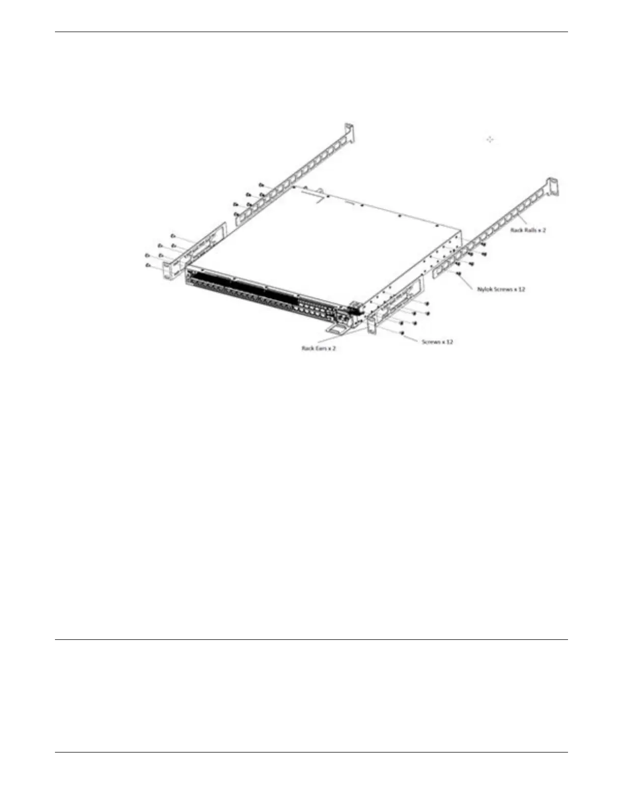
5. Slide the rack rails into the rack ears on both sides, and adjust them to the
appropriate rack depth.
Figure 22: Attaching the Side Rails
6. Attach the rack rails to the rear rack posts, using the rack screws (not provided).
7. If a grounding lug is present, ground the switch.
a. At one end of the wire, strip the insulation to expose 1/2 inch (12 mm) of bare wire.
b. Identify the grounding lug on the back of the switch.
c. Insert the stripped wire into the grounding lug.
d. Tighten the retaining screw with a straight-tip torque screwdriver to 20 in-lb (2.25
N m).
e. Connect the other end of the wire to a known reliable earth ground point at your
site.
After the switch is secured to the rack or cabinet, install optional components using the
instructions in Installing Optional Components on page 49.
After installing optional components, install one or two power supplies using the
instructions in Installing Internal AC Power Supplies on page 50.
Installing Optional Components
After the switch is secured to the rack, install optional components.
ExtremeSwitching switches support the use of pluggable transceivers and cables in the
SFP+, SFP28, QSFP+, and QSFP28 formats.
For a list of the optical components supported with ExtremeSwitching devices, see the
Extreme Optics website.
Installing a Switch Installing Optional Components
VSP 4900 Series Switches: Hardware Installation Guide 49
 Loading...